Send Your RFQ to Synbase Steel
Prefer to send drawings, BOMs or attachment lists by email? sales@synbasesteel.com

| Governing standard | ASME B36.10M (carbon/alloy) & B36.19M (stainless) |
| Size range | NPS 1/8″ to 48″ (OD 0.405″ – 48.000″) |
| Schedule range | 5S, 5, 10S, 10, 20, 30, 40S/STD, 40, 60, 80S/XS, 80, 100, 120, 140, 160, XXS |
| Line-pipe overlay | API 5L PSL1/PSL2 (47th Edition, June 2026), references the same B36.10M dimensions |
| Weight formula | W = 10.69 × (OD − t) × t (lb/ft, plain-end steel pipe) |
A pipe schedule chart is the standardized ASME B36.10M table that maps a nominal pipe size (NPS) and schedule number to the resulting outside diameter, wall thickness and weight per foot for both carbon and alloy steel pipe — also known as a pipe size chart or steel pipe size chart. Engineers and buyers use it to transform a two-part dimensional callout – “NPS 4 x Schedule 40” – into the actual dimensions a mill cuts, and to confirm a pipe rated for one service pressure isn’t substituted for a weaker-walled one on a subsequent purchase order.
Schedule number dictates wall thickness, not OD: at a given NPS, OD is constant regardless of schedule (e.g., 2 NPS is always 2.375 OD) and wall grows from 0.109 in Schedule 10 to 0.436 in XXS – six different pressure ratings with an identical fitting bore.
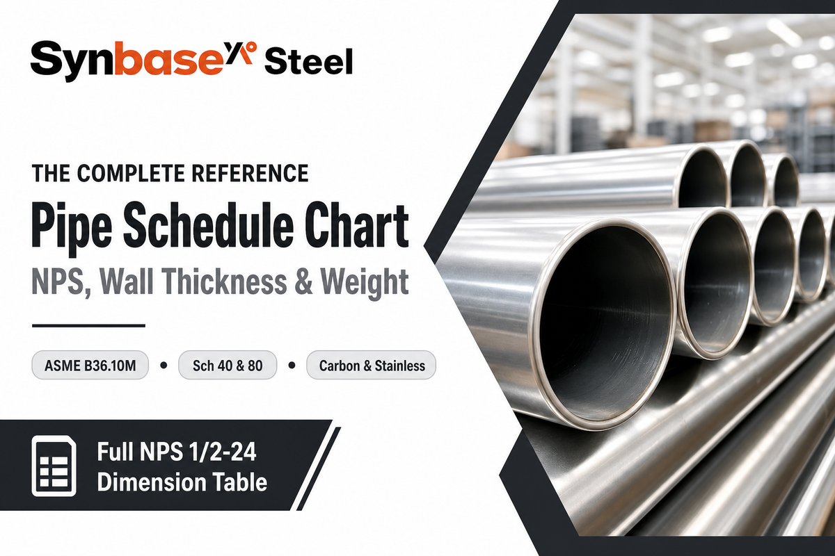
Need a standard pipe schedule chart PDF to print, or a pipe schedule chart Excel version to drop into your own takeoff sheet? Some engineers just call it a sch pipe chart for short, and a pipe size chart schedule 40 lookup is usually the single row they’re after. The table below, showing data for NPS 1/2-24 at Schedule 40 and 80, can be printed straight from this browser window or copied into Excel for shop-floor or bid use.
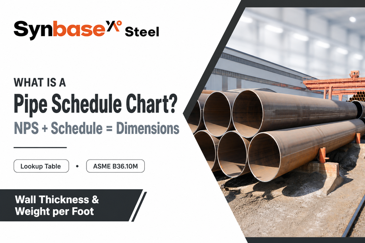
A lookup table in accordance with ASME B36.10M that indicates the wall thickness, outside diameter, and weight per foot corresponding to any combination of nominal pipe size (NPS) and schedule number. Such a table is required because calling out a pipe simply by its “diameter” can lead to ambiguity: a “4-inch line” could be Schedule 40 (0.237 inch wall) or Schedule 160 (0.531 inch wall) – and one weighs more than twice as much as the other.
There are two related standards for this data: B36.10M covers carbon and alloy steel pipe and B36.19M covers stainless steel pipe (with a separate schedule system, including designations with “S,” shown below). Line-pipe purchasers must use this information in conjunction with API 5L specifications for pipe destined for oil and gas transmission services.
“A schedule callout on a drawing is only as useful as the chart behind it. We’ve had spool packages rejected at receiving inspection because someone matched the wrong schedule column to the wrong nominal size, the chart has to be read as NPS first, schedule second, never the other way around.”
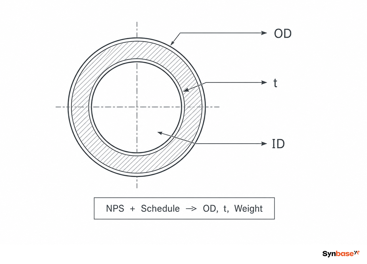
Skipping straight to a single row without checking the schedule column is a common way buyers end up ordering the wrong wall thickness. Some readers search for this table as a “pipe schedule and thickness chart” rather than by its formal name — both point to the same data. The table below provides data for sizes which represent by far the largest majority of plant, structural and transmission piping orders, from NPS ½ through 24, at both Schedule 40 and Schedule 80, with dimensional information cross-referenced to the issued ASME B36.10M dimensional series. Weight has been derived using the basic plain end weight formula: W = 10.69 × (OD − t) × t (lb/ft), with OD and t measured in inches.
| NPS | OD (in) | Sch 40 Wall (in) | Sch 40 Wt (lb/ft) | Sch 80 Wall (in) | Sch 80 Wt (lb/ft) |
|---|---|---|---|---|---|
| 1/2″ | 0.840 | 0.109 | 0.85 | 0.147 | 1.09 |
| 3/4″ | 1.050 | 0.113 | 1.13 | 0.154 | 1.48 |
| 1″ | 1.315 | 0.133 | 1.68 | 0.179 | 2.17 |
| 1-1/4″ | 1.660 | 0.140 | 2.27 | 0.191 | 3.00 |
| 1-1/2″ | 1.900 | 0.145 | 2.72 | 0.200 | 3.63 |
| 2″ | 2.375 | 0.154 | 3.66 | 0.218 | 5.03 |
| 2-1/2″ | 2.875 | 0.203 | 5.80 | 0.276 | 7.67 |
| 3″ | 3.500 | 0.216 | 7.58 | 0.300 | 10.26 |
| 4″ | 4.500 | 0.237 | 10.80 | 0.337 | 15.00 |
| 5″ | 5.563 | 0.258 | 14.63 | 0.375 | 20.80 |
| 6″ | 6.625 | 0.280 | 18.99 | 0.432 | 28.60 |
| 8″ | 8.625 | 0.322 | 28.58 | 0.500 | 43.43 |
| 10″ | 10.750 | 0.365 | 40.52 | 0.593 | 64.40 |
| 12″ | 12.750 | 0.406 | 53.60 | 0.687 | 88.60 |
| 14″ | 14.000 | 0.437 | 63.35 | 0.750 | 106.20 |
| 16″ | 16.000 | 0.500 | 82.85 | 0.843 | 136.60 |
| 18″ | 18.000 | 0.562 | 104.70 | 0.937 | 170.90 |
| 20″ | 20.000 | 0.593 | 123.00 | 1.031 | 209.00 |
| 24″ | 24.000 | 0.687 | 171.20 | 1.218 | 296.60 |
Sizes 1/2 – 8 were double checked against two independent, published sources. For size 10 and greater, wall thickness data is taken from ASME B36.10M and the weight is calculated from the above formula. That same standard also publishes additional schedules not shown above (5, 10, 20, 30, 60, 100, 120, 140, and 160) using the identical wall-thickness series.
This calculation derivation in the two sections below will enable you to solve for any wall thickness, all based on the same original standard instead of searching through another PDF.

Ordering by NPS alone is one of the more common mix-ups a buyer makes: NPS (Nominal Pipe Size) isn’t an actual measure of diameter, but a designation, and anything less than NPS 14 isn’t equal to the pipe’s O.D. A buyer who assumes “2-inch pipe” means a 2.000-inch OD ends up with a bore mismatch at the jobsite: a “2-inch pipe” actually has an O.D. of 2.375 inches, and a “12-inch pipe” has an O.D. of 12.750 inches.
From NPS 14 up to 48, the NPS number equals the outside diameter.
But the NPS 14 divergence from standards is old, not whimsical. Early iron pipe was ordered to outside dimension, and for small sizes OD-ID difference was so significant that pipe made to iron-pipe sizes (IPS) has persisted even as steel dimensions (and ordering practices) became standard. But for NPS 14 and larger, OD and ID approach the same number, and ASME continued to match the new (actual OD) standard rather than redo drawings of centuries of equipment.
DN, the metric equivalent (nominal diameter, from the French diamètre nominal), is usually remembered by the rough rule DN = 25 × NPS to simplify calculation in one’s head. It works pretty nicely at small sizes (DN15 to 1/2-in; DN50 to 2-in), but the relationship isn’t always that close (as in multiples of 25) at every size; DN and NPS were both standardized separately, then aligned imperfectly.
This is close enough for informal chats about sizes, but you still need to check a European drawing to find the real DN size. Outside North America, the same dimension is sometimes labeled NB (Nominal Bore) rather than DN — both refer to the metric nominal bore, not the actual measured diameter.
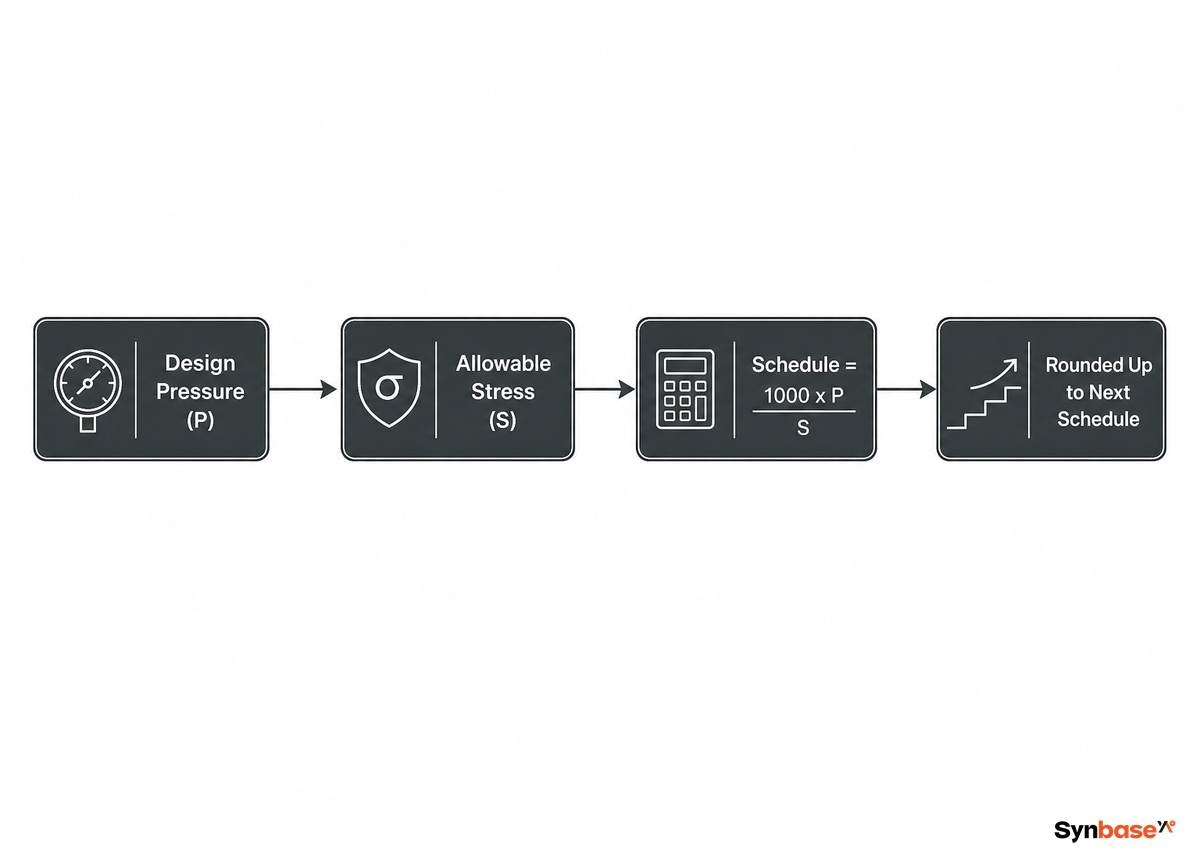
Pipe wall thickness – and the schedule number used to identify it – are determined by the ratio of design pressure to material allowable stress under piping design codes like ASME B31.3, not by an arbitrary set of integers: Schedule ≈ 1,000 × P / S, where P is the design pressure (MPa) and S is the allowable stress of the pipe material at design temperature (MPa).
This dimension table in B36.10M is, itself, a list of wall thicknesses rather than a working formula, but the design principle underlying that table is still based on the calculation: higher P/S results in higher schedule number. One NPS will therefore appear across an entire range of wall thicknesses rather than just one value.
Worked example: a carbon steel line intended to operate at 6.9 MPa (1,000 psi) on A106 Grade B pipe with an allowable stress of about 137.9 MPa at the design temperature works out to: Schedule ≈ 1,000 × 6.9 / 137.9 ≈ 50. Since schedules are available only in increments, the specifying engineer rounds up to the next higher available schedule – 60 – not down, thus ensuring the pipe wall will never be thinner than necessary. That one division is, in practice, most of the math behind every schedule number on a piping specification.
Design engineers would almost never derive this formula from zero for typical plant piping. Instead, they pick an available standard schedule off the table and check it against the appropriate material/temperature allowable stress from the ASME B31.3 table, rather than working backwards to calculate a custom wall thickness for a single order.
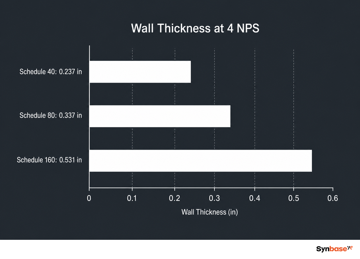
Schedule 40 is used for most low-to-moderate pressure plant and structural pipe; Schedule 80 goes to the next level for higher-pressure or corrosion allowance service; Schedule 160 and XXS is only used for high-pressure or severe service linepipe that must still maintain sufficient thickness at the end of its service life, following the same ASME B31.3 allowable-stress logic covered above.
The only things different in all 3 of these schedules is bore and wall thickness for any NPS; the OD is the same, so a thicker Schedule 80 wall necessarily narrows the inside diameter compared to Schedule 40 at that same NPS.
Named framework: the 3-Factor Schedule Selector — before you reflexively resort to the “we’ve always used Schedule 40” mentality, compare the required design pressure against the material’s allowable stress, determine your design temperature (allowable stress declines with increasing temperature, a trend that can move your design schedule upward at a given pressure), and apply a corrosion allowance to anything that’s not a perfectly clean, dry, non-corrosive service. Any one of those three factors working against you is reason enough to step up a schedule, and a higher schedule number by itself isn’t a substitute for actually checking them. As fabricators noted in an online forum discussion, you can achieve the same service result with a thinner, smoother-bore SDR-rated pipe wall as with the corresponding numbered schedule pipe, precisely because schedule number alone doesn’t capture bore geometry or material differences.
Procurement teams who fail this step will regret it later – twice. One steel-pipe distributor’s own purchasing guide identifies “choosing a Schedule 80 pipe when a Schedule 40 pipe would suffice” as a top, costly procurement gaffe: over-specifying uses money for unnecessary steel mass as surely as under-specifying leads to a rejected spool. A fabrication trade-group blog is blunt about the consequences of the latter: “A mismatched heat number, pipe grade or schedule can lead to the full acceptance or rejection of a whole spool.”
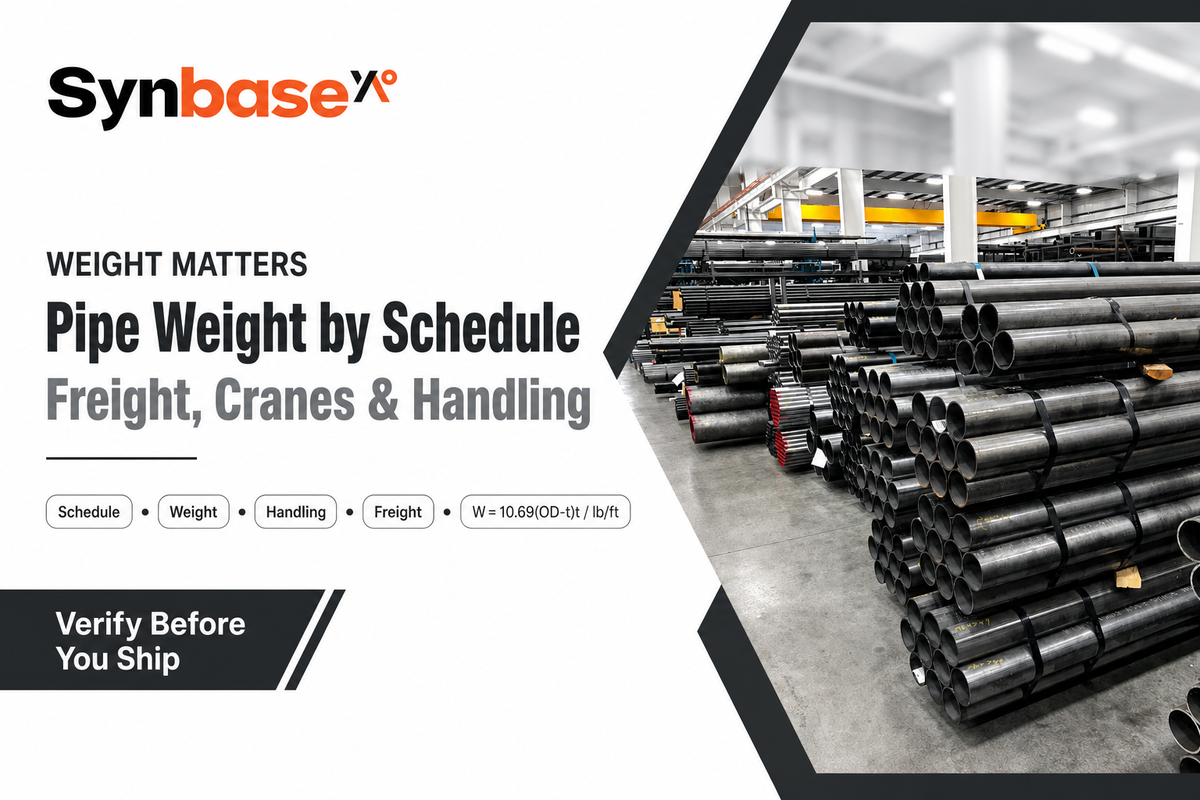
Plain-end steel pipe mass calculation: W = 10.69 × (OD − t) × t, where W is the mass in lb/ft, OD is the outside diameter in inches, and t is the wall thickness in inches. This same basic mass equation defines the weight tables published alongside the ASME B36.10M dimensional series. Example: for 4 NPS Sch. 40 pipe (OD 4.500 in, t 0.237 in): W = 10.69(4.500 – 0.237)(0.237) = 10.69(4.263)(0.237) = 10.80 lb/ft (the value shown in the above chart and a value well worth verifying before taking any weight per foot on a quote as fact).
Weight per foot is more than just a mill spec. It influences the freight class of your shipments; dictates the crane and rigging capacity needed at your job site; and determines how many joints fit on a truck without exceeding mixed-load weight limits. Weight per foot also helps the pipe distributor quote pricing per-bundle, offloading freight-and-handling costs with that precise number — and a seemingly minor upgrade in pipe schedule on a design drawing could potentially shift a project’s logistics budget more than its material budget.
No desire to manually calculate weight? Synbase’s own pipe weight calculator and the family-specific SMLS pipe weight calculator apply the same formula across the full NPS and schedule range, including sizes and materials not shown in the table above.
Field crews run into this constantly on retrofit and repair jobs: a length of pipe shows up on site with no mill cert or stencil, and the crew has to decide whether to weld in a matching replacement or call it out for testing. A crew that guesses wrong and welds in a lighter-schedule replacement on a live steam line finds out the hard way at the next hydrotest. Lacking a mill cert or a stencil to read on the pipe, you can deduce NPS and schedule from two readily measured pipe attributes: its OD and wall thickness. Use a caliper to measure the outside diameter of the pipe end and compare the result to the OD column above to identify the pipe’s NPS; then measure the pipe’s wall thickness at the cut end and compare that value to the schedules listed under that same NPS — your pair of measurements should match one, and only one, cell in the chart.
The Field Schedule Verification Method: (1) caliper the OD at the pipe end, not the middle of the length where a scale build-up can affect the measurement; (2) measure the wall thickness at two 90° spaced locations and average, because the rolling tolerance can vary around the circumference; (3) cross-reference the two readings to the appropriate chart and identify the NPS and schedule number; (4) if the pipe has a mill test report, confirm the heat number on the pipe body to the MTR before calling the identification complete; (5) if any pipe is destined for pressure service, treat a caliper measurement as a field verification and not as a replacement for traceable inspection.
The disciplines of verifying wall thickness are developing areas of expertise. Ultrasonic and magnetic flux leakage methods of detecting wall loss are subject to ongoing patents (for example, US 2009/0243604, a magnetic-flux-leakage pipe-wall-thickness measurement method) and industry technical literature. That should highlight why a one-off caliper measurement serves as a point of departure in the identification process rather than as a replacement for a documented in-service inspection.
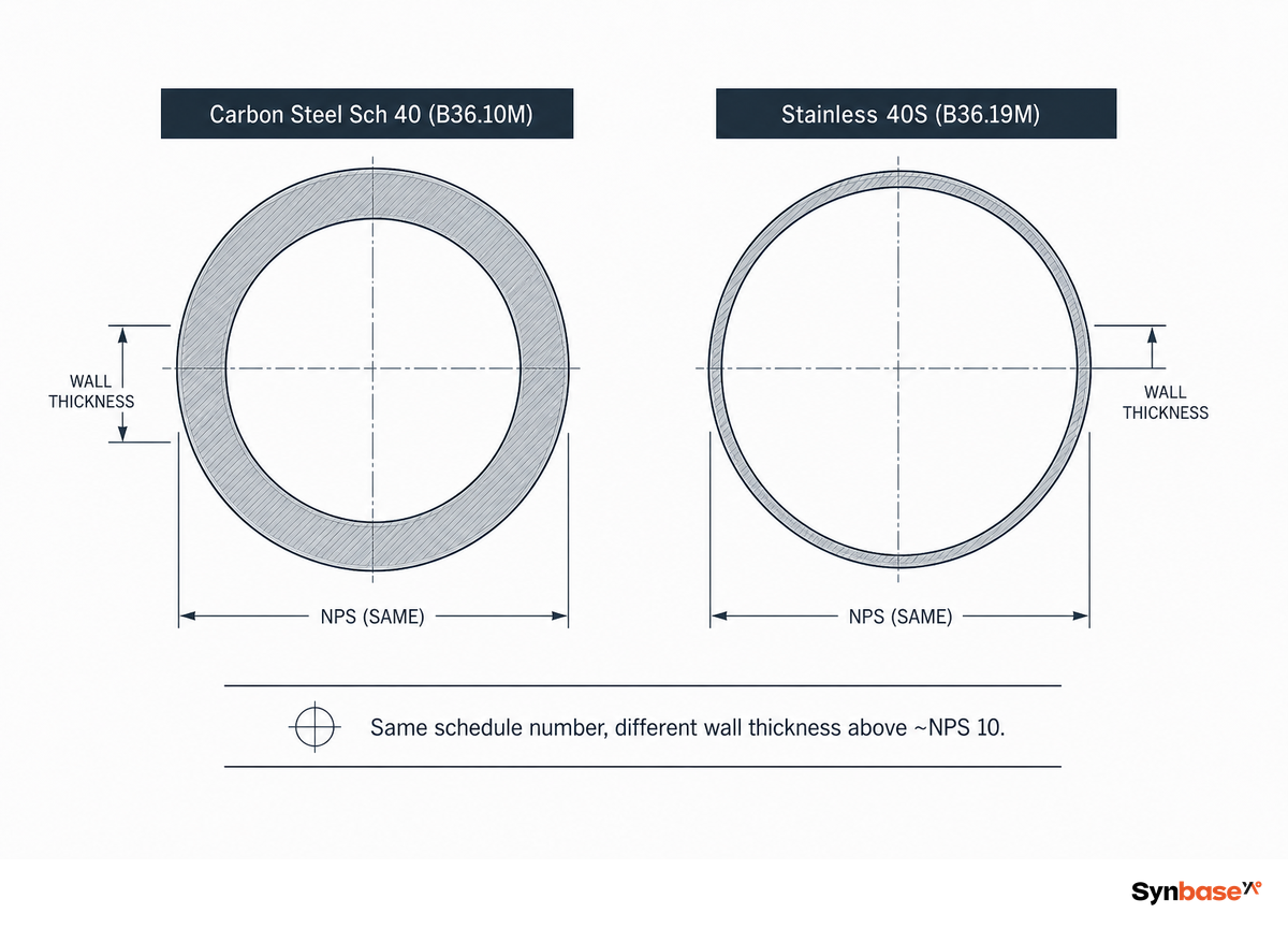
Looking at a pipe schedule chart stainless steel version side by side with a carbon-steel one, the numbers don’t line up the way you’d expect: a stainless steel pipe schedule chart isn’t just a carbon-steel chart with a different label. While schedule number is a geometric characteristic common to all materials, the allowable pressure at that schedule varies from material to material. And stainless pipe uses a somewhat different wall thickness series in the first place. Per ASME B36.19M (the stainless specification), schedules have an “S” suffix (5S, 10S, 40S, 80S) and at anything larger than about NPS 10, the stainless wall-thickness schedule series begins to differ from the B36.10M carbon steel series with the same schedule number. For instance, a 40S stainless pipe won’t be dimensionally identical to a Schedule 40 carbon steel pipe with the same NPS — a mistake that shows up as a fitting that won’t seat properly once it reaches the shop.
The allowable pressure associated with a given schedule number is also dependent upon how the pipe was manufactured, not solely upon the material. Per B31.3 (the code of construction for chemical plants and refineries), SMLS pipe, pierced from a solid billet, with no weld seam, carries a joint-quality factor (E) of 1.00. Standard electric-resistance-welded (ERW) pipe has a joint-quality factor (E) of 0.85. This means an SMLS pipe of identical NPS, schedule and material grade can carry roughly 20% higher internal pressure than the ERW pipe. B31.3 doesn’t permit that value to be raised for ERW by merely augmenting the inspection, because the seam itself is the weakest link, which is why the same schedule number represents a different pressure ceiling depending on the manufacturing method, and not just the material grade.
| Material family | Common grade | Schedule series | Notes / limitations |
|---|---|---|---|
| Carbon steel | ASTM A106 / A53 | B36.10M (5–160, STD/XS/XXS) | Not for cryogenic or sour service without added spec |
| Stainless | ASTM A312 (304/316) | B36.19M (5S–80S) | S-series wall differs from carbon series above ~NPS10 |
| Cr-Mo alloy | ASTM A335 (P11/P22/P91) | B36.10M series | Not suitable below rated creep-service temperature |
| Low-temperature | ASTM A333 Gr 6 | B36.10M series | Requires Charpy impact testing for cryogenic service |
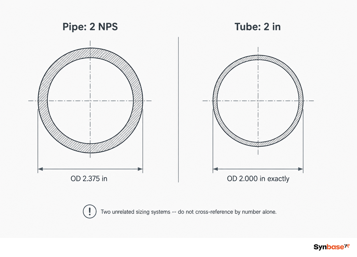
Pipe and tube use a fundamentally different sizing approach, and a 2-inch description means two different things in each case. Pipe is identified by nominal NPS (nominal pipe size) and schedule number, where OD is standardized according to size under ASME B36.10M/B36.19M. Tube is sized according to the actual, measured outside diameter, often specified with a gauge number instead of a wall thickness, without the intermediate step of nominal designation. 2 NPS pipe has an OD of 2.375 inches, whereas 2 tube has an OD of exactly 2.000 inches. This mix-up is a genuine, recurring purchasing error: a buyer who orders “2-inch” fittings for a 2-inch tube run, sourcing off a pipe schedule chart, receives connectors sized for a 2.375-inch OD pipe that simply won’t fit. Unless you’re certain whether you’re dealing with pipe or tube, a cross reference of the pipe chart against a tube size chart will guarantee you order the wrong fitting.
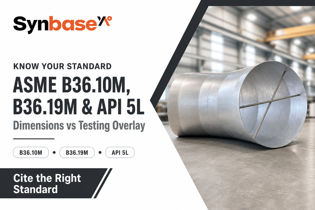
Citing the wrong standard on a purchase order is a common, expensive mix-up: ASME B36.10M details dimensions for welded and SMLS wrought carbon and alloy steel pipe; ASME B36.19M is for stainless; and API 5L (most recently the 47th Edition, published in June 2026 with added specifications in HFW weld quality, sour service testing, CO2 transmission pipeline service, among others) overlays line-pipe-specific PSL1/PSL2 tests – impact testing, NDT per-pipe, hydrostatic testing – on the B36.10M dimensional standards rather than a distinct sizing convention. A pipe marked as API 5L PSL2 and a pipe marked as only ASME B36.10M could both have the exact same NPS, schedule, OD, and wall thickness-the difference is purely in the tests conducted and recorded on the certificate, not in the numbers on a dimensional chart.
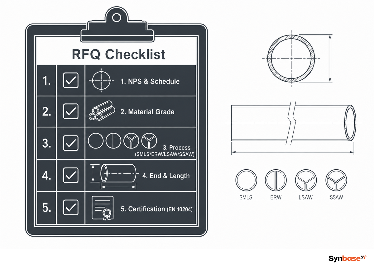
Once a pipe size is specified together with a schedule number from a table, the quickest way to receive an accurate mill quotation is by providing the same five pieces of information that a mill needs for any quotation – rather than simply supplying a nominal size and assuming a mutual understanding of what “standard” means. Whether you’re ordering bare pipe or the pipe fittings (elbows, tees, reducers) that connect to it, the same rule applies — the fitting’s schedule must match the pipe’s.
RFQ checklist — copy these into your quote request:
| Parameter | Recommended range | Why it matters | How to verify |
|---|---|---|---|
| NPS & Schedule | e.g. 4″ NPS Sch 40 | Fixes OD, wall, and weight simultaneously | Cross-check both numbers against the chart together |
| Material / grade | A106 Gr B, A312 TP316, etc. | Sets allowable stress and schedule-series (B36.10M vs B36.19M) | Match ASTM/ASME grade on the MTR |
| Process (SMLS/ERW/LSAW/SSAW) | Per service pressure & OD | Weld joint factor changes allowable pressure at the same schedule | Confirm ASME B31.3 E-factor used in design |
| End & length | Plain/bevelled, SRL/DRL | Affects fit-up and freight count | State explicitly, don’t assume “standard” |
| Certification | EN 10204 3.1 or 3.2 | Heat-number traceability for the exact pipe shipped | Match heat number on the MTR to the pipe body stencil |
Synbase created this resource because our sales team fields inquiries from EPC clients across the USA and abroad about which schedule is “needed” on a regular basis, and many published charts (some labeled simply “Sched.” tables) don’t extend beyond Schedule 40 and 80, nor do they explain how those figures are derived.
Our goal is a single reference that lets a buyer cross-check schedules and sizes together instead of hunting through several separate PDFs. Synbase manufactures in-house SMLS, ERW, LSAW, and SSAW pipe, so the distinctions for pressure rating and material type listed below reflect the specifications we use for our own mill orders.
Synbase Steel supplies steel pipe, fittings, flanges, valves and OCTG for oil and gas, petrochemical, power, water and industrial projects. Our technical guides are written to help buyers compare standards, grades, dimensions, coatings, inspection requirements and commercial terms before sending an RFQ.
We focus on practical specification work: matching pipe process to service conditions, checking wall thickness and end finish, reviewing MTC and NDT requirements, and clarifying documentation before production or shipment.
Project support across seamless pipe, ERW, LSAW, SSAW, buttweld fittings, forged flanges, valves and oilfield tubulars.
Specification review for ASTM, ASME, API, EN and DIN standards, including material grade, pressure class, coating and inspection scope.