Send Your RFQ to Synbase Steel
Prefer to send drawings, BOMs or attachment lists by email? sales@synbasesteel.com

On a steam, hydraulic and instrumentation line the socket weld flange is the right choice where a threaded joint could leak and a slip-on could fatigue – assuming the correct class, correct bore and correct gap and weld. Synbase Steel forges, machines and certifies every form of SW and RFSW flange across all pressure classes. Along with our material test certificates your inspector will sign off the line to get you producing.
Request an RFQ Quote →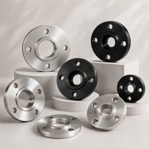
A socket weld flange is a welded flange fitted with a bored shoulder, or counterbore, on the inside face of the bore. The pipe is slipped in until it bottoms on the shoulder, the welder back it up slightly about 1/16 inch (1.6 mm), and it is attached with a single fillet weld around the outside. It’s this recessed pipe with an outside weld only that explains the origins of the SW for high pressure-small bore piping applications: the weld penetrates no part of the bore itself, eliminating the risk of a cracked root bead, and leaving nothing inside to capture product.
The problem the joint solves is real. In a 1in or 1.5in high-pressure line, a flanged joint is a threaded joint; the tapered threads must mate tight and seal with a gasket compound which is susceptible to vibrational and thermal breakdown; every tiny weep indicates a remake job. And a same sized slip-on joint provides only two-thirds of the fatigue life that same joint has under load but has exactly the same static strength. The socket weld flange does both: it puts that greater strength and reliability in the line in which the fitter has the least space to work.
This page is written for the choice a specifying engineer faces, the choice isn’t ” What is a socket weld flange?” It’s which class and bore your line requires, whether SW is the right choice, and how to certify and land the part without an unpleasant invoice.
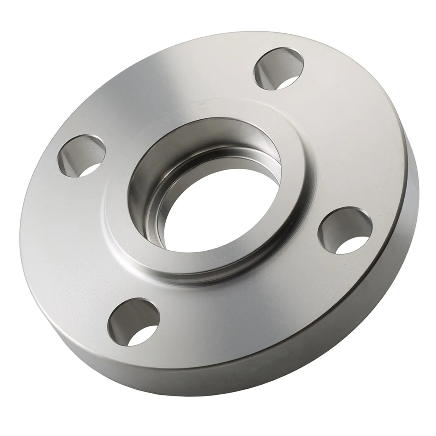
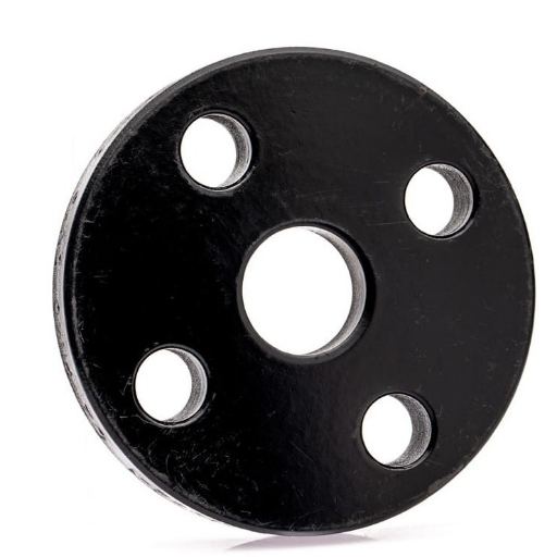
Each Synbase socket weld flange starts as one piece of bar stock material (ASTM A105 for carbon steel, A182 for stainless and alloy). This bar is then machined so that the counterbore perfectly aligns to the OD and schedule of the connected pipe. Forging on a high pressure connection is key — a forged hub, being comprised of one continuous grain with inherent directionality, is what underpins the basis for the ASME B16.5 pressure-temperature rating; in contrast to one derived from a block of cut plate. In ASME B16.5, the socket weld is only enumerated through NPS 3, beyond which it transitions to a weld neck, meaning this item clearly belongs to small-bore piping, and is right at home where it excels.
ASTM A105 · Class 150–2500 · RF/FF · 1/2″–3″
A182 F304/L · F316/L · Class 150–1500 · RF/RTJ
A350 LF2 · A182 F11/F22/F91 · Class 150–2500
Reducing SW · orifice SW · SAE J518 code 61/62
Besides the conventional raised face flange, the very same forging is also the beginning for most other modifications that are demanded by design engineers. A reducing flange socket weld is able to connect two different line sizes without an extra reducer, a socket weld orifice flange allows differential-pressure flow taps, whereas socket weld flanges to SAE J518 code 61 (3000 psi) or code 62 (6000 psi) are used in hydraulic power systems where the connection is made by a four-bolt pattern at the SAE boss onto an internally welded stud, the seal being made by RF, RTJ or flat faces against their mate.
| If your line is… | Material | Face | Typical class |
|---|---|---|---|
| Steam, condensate, utility | CS A105 | RF | 150–600 |
| Hydraulic / lube-oil power | CS A105 | RF / SAE flange | 600–2500 |
| Low-temperature / cryogenic | A350 LF2 | RF | 150–1500 |
| Chemical / instrument (non-crevice) | SS A182 F316/L | RF | 150–900 |
| High-pressure injection / wellhead small-bore | Alloy F11–F22 | RTJ | 1500–2500 |
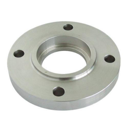
A socket weld flange only does its job when the OD, thickness, bolt circle and hole pattern of mating flange are identical, and socket bore equals the connecting pipe OD for a particular pipe schedule. The tables below summarize requested ASME B16.5 dimensions in millimetres for the small bore size range, and the remaining dimensions for class 600, 1500 and 2500 – plus socket weld bolt lengths – are provided on the downloadable specification sheet. An often overlooked purchase detail at final inspection is that ASME B16.5 hole patterns remain identical across revisions, while specifications for material and marking differ – we supply to the current issue and note this on our certificate.
| NPS | Flange OD | Thickness | Hub OD | Socket bore | Socket depth | Bolt circle | Bolts |
|---|---|---|---|---|---|---|---|
| 1/2″ | 90 | 9.6 | 30 | 22.2 | 10 | 60.3 | 4 x 1/2″ |
| 3/4″ | 100 | 11.2 | 38 | 27.7 | 11 | 69.9 | 4 x 1/2″ |
| 1″ | 110 | 12.7 | 49 | 34.5 | 13 | 79.4 | 4 x 1/2″ |
| 1-1/4″ | 115 | 14.3 | 59 | 43.2 | 14 | 88.9 | 4 x 1/2″ |
| 1-1/2″ | 125 | 15.9 | 65 | 49.5 | 16 | 98.4 | 4 x 1/2″ |
| 2″ | 150 | 17.5 | 78 | 61.9 | 17 | 120.7 | 4 x 5/8″ |
| 3″ | 190 | 22.3 | 108 | 90.7 | 21 | 152.4 | 4 x 5/8″ |
| NPS | Flange OD | Thickness | Hub OD | Socket bore | Socket depth | Bolt circle | Bolts |
|---|---|---|---|---|---|---|---|
| 1/2″ | 95 | 12.7 | 38 | 22.2 | 10 | 66.7 | 4 x 1/2″ |
| 3/4″ | 115 | 14.3 | 48 | 27.7 | 11 | 82.6 | 4 x 5/8″ |
| 1″ | 125 | 15.9 | 54 | 34.5 | 13 | 88.9 | 4 x 5/8″ |
| 1-1/2″ | 155 | 19.1 | 70 | 49.5 | 16 | 114.3 | 4 x 3/4″ |
| 2″ | 165 | 20.7 | 84 | 61.9 | 17 | 127.0 | 8 x 5/8″ |
| 3″ | 210 | 27.0 | 117 | 90.7 | 21 | 168.3 | 8 x 3/4″ |
The depth of socket in the tables dictates how far pipe extends inside the fitting; the built-in safeguard against stress during operation is the socket bottoming gap. Pipe inserted until its ends touch the fitting’s internal shoulder, then withdrawn by ~ 1/16″ (1.6 mm) prior to tacking allows the pipe to expand under operating conditions without stressing the root of the fillet weld. Failure to provide this clearance results in the pipe and fitting body sharing the direct thermal stress, a common mechanism leading to socket-weld cracking which is addressed by ASME B31.1 and B31.3 fabrication regulations. At Class 600 and above, the raised face grows to 7 mm, and fitting thickness increases significantly – for example, a 2″ Class 1500 flange is almost twice the thickness of its 150# equivalent at 38 mm versus 17.5 mm – it’s the high-pressure brute force.
When a project specifies the connecting pipe schedule, match it to the socket bore: Schedule 80/160 pipe, with its higher wall thickness and corresponding reduced bore, must still slip fully into its sockets, and therefore needs larger bore size sockets for its outside diameter. We verify pipe OD against socket bore at quotation stage to prevent a large diameter pipe being purchased to fit a smaller, standard size bore size socket on a flange.
The four types of small to mid-bore flange below compete for much the same work, and fitting the wrong kind is one of the piping industry’s most frequent – and most costly – mistakes once installation is complete. They differ from one another in function and performance, rather than mere adjectives. Socket welds offer the same load capacity and twice the fatigue strength of slip-ons, due to the external fillet’s resistance to bending stresses. At roughly 10% greater cost than the slip-ons they displace, socket welds become even more economical if the line must eventually operate at pressures greater than can be borne by the slip-ons or the fatigue strength of those joints. Threaded fittings are chosen primarily because they do not require welding, enabling installation in locations where a hot work permit is not feasible but making joints susceptible to vibration leaks. Weld necks provide superior strength and are the appropriate choice when the bore size is beyond the small-end of the SW range or where joints are subject to full radiographic examination.
| Property | Socket Weld | Slip-On | Threaded | Weld Neck |
|---|---|---|---|---|
| Typical size range | 1/2″–2″ (to 3″) | 1/2″–24″ | 1/2″–4″ | 1/2″–60″ |
| Static strength | Equal to slip-on | Baseline | Lower | Highest |
| Fatigue strength | ~50% above slip-on | Baseline | Low | Highest |
| Welds required | 1 external fillet | 2 fillets | None | 1 full butt weld |
| Full-penetration / radiography | No (fillet only) | No | No | Yes |
| Relative initial cost | ~1.1x slip-on | 1.0x baseline | ~0.9x | 1.5–2x |
Understand the table from top down based on your duty. For a high-pressure 1” steam or hydraulic line for which a fitter has very little working space, a socket weld is superior for its strength under cyclic load and its leak integrity. For that same line in a crevice-prone fluid, a weld neck or even blind flange may be better. For a 6” line, it’s between a weld neck and a slip-on – size makes the socket weld unsuitable by definition. As a matter of policy, as well as practice, Synbase provides all three.
Weighing socket weld against a slip-on or weld neck for a specific line?
Request a recommendation →
The Socket Weld Flange. These connections typically “earn their stripes” on small-bore, high-pressure, and/or high vibration services – power station superheated steam and condensate, hydraulic, and lube oil; instrumentation and impulse lines; chemical injection skids and fuel gas runs. Usually in service sizes up to 2 inches and smaller, the socket weld concept dates to its successful development for stainless steel superheater service, where its unpenetrated bore was less susceptible to the thermal fatigue cracking that characterized small bore, welded connections in those services. They are indeed the default connections used in those specific small-bore services by many process engineers.
It’s equally if not more important to know when the socket weld connection is “the wrong thing to do”, and those guidelines were developed from lessons learned from field experiences to protect your process. ASME B31.3 has a clear warning against socket welded connections for any corrosive fluid which will pit the flange and the piping, as evidenced by the created crevice between the pipe O.D. and socket corner, which forms a stagnant zone prone to pitting. The same caution applies to applications with high vibration, erosive services, or those in severe cyclically stressed piping. Those lines usually call for a full-penetration butt-welded connection such as a weld neck; a socket weld would still create a crevice and is therefore not preferable. Two other specific design limits are worth noting: first, the socket weld joint uses a fillet weld which is not a full penetration weld, meaning it can’t be radiographed for quality assurance like other full penetration joints; second, where the “root” of the weld extends inside the pipe within the socket, an internal crack could initiate there and go unseen by inspection of the outside of the joint. High integrity lines thus generally call for a weld neck whose butt weld can be fully examined for quality.
“We tell a lot of customers what we tell our guys in the shop, that the socket weld makes a great high pressure instrument connection and the absolute wrong connection for a sour gas and chloride containing fluid. If the process liquid is going to pit the stainless flange, we’re going to be making a weld neck for you, and explain the reasoning, as lost business on a poorly chosen flange is cheap compared to a process interruption and the field repair that may ensue.
Synbase Steel Engineering Team, Flange & Forging Division
Ultimately, the distinction separates the supplier who fulfills your purchase order from the one who fulfills your project’s needs. When socket welds are incorrect for service, then either a weld neck flange or a capped blank may be the best selection, all manufactured in one plant from the same stock material.
The quickest way to clock up a week’s delay on site; a socket weld flange with no UT papers. Procurement report the same: a supplier declares a grade, fails to produce matching certification on goods-in, and the batch is put on hold as the line grinds to a halt. Synbase bridges that gap on the production line. Every delivery runs with an EN 10204 3.1 Material Test Certificate – chemical analysis, mechanical properties and heat-treatment record verified by our works – and the heat number branded on the flange so the inspector can trace the part back to the mill melt that cast it. Our projects with designated need also receive EN 10204 3.2 certificates witnessed by recognized third-party inspection agencies.
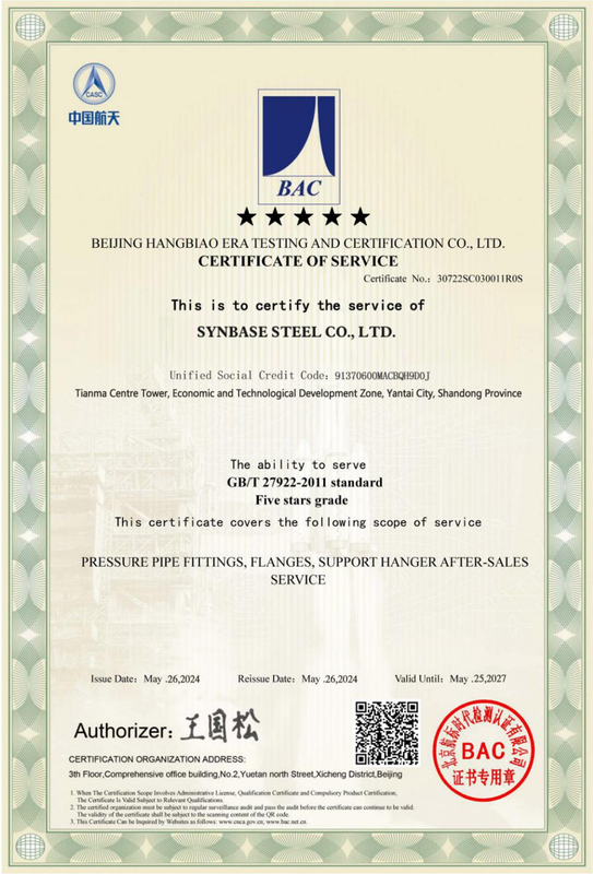
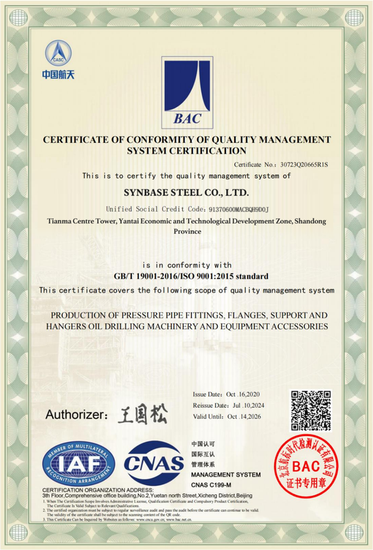
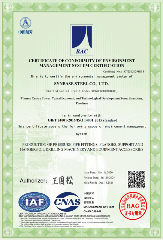
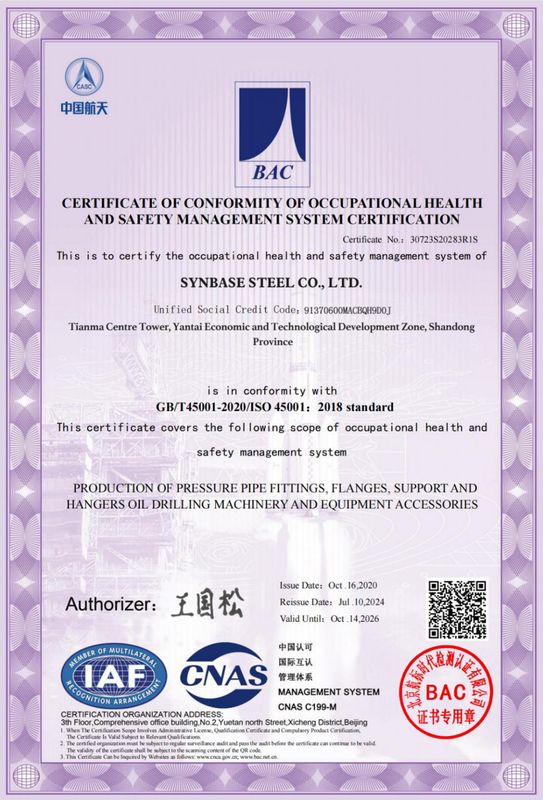
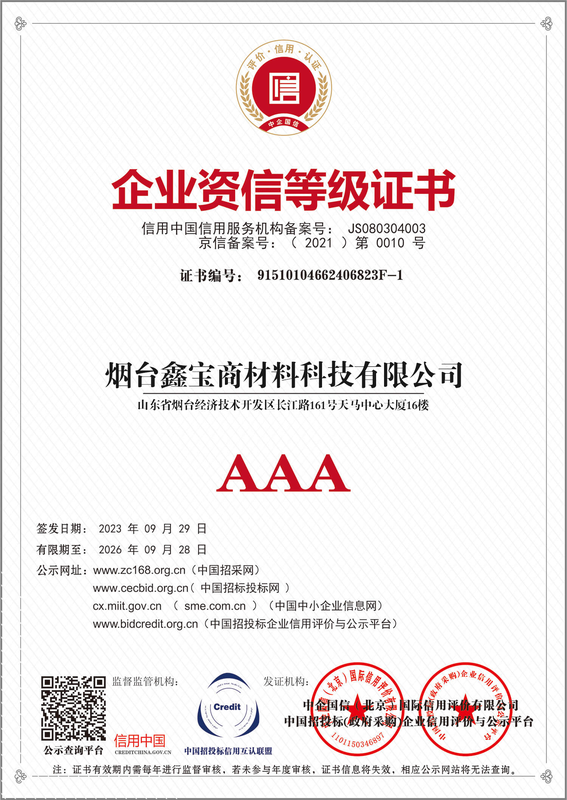
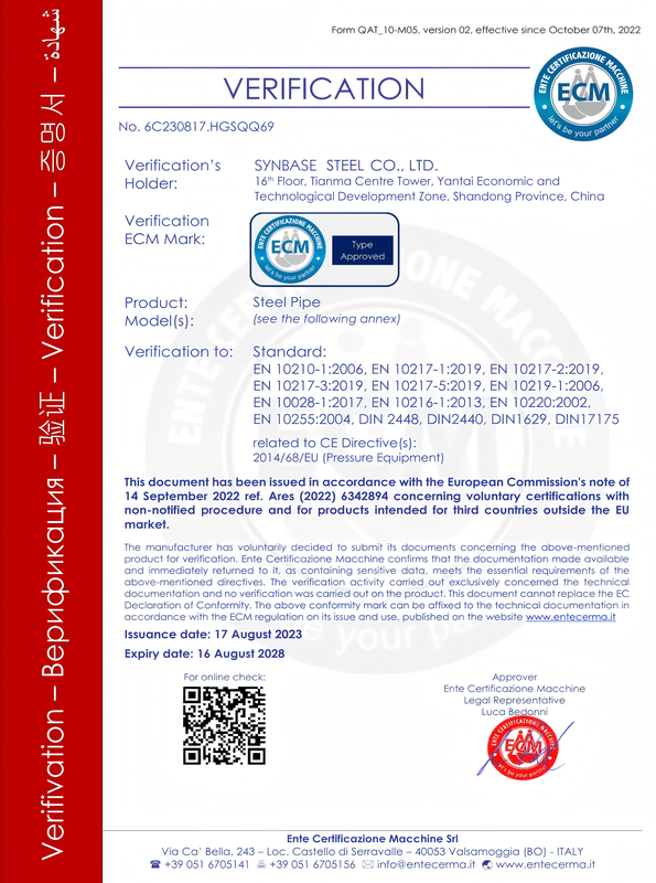
The reason your specs have badges is in the structure; Synbase is the fundamental flange business of our central production group, a producer of steel pipes, pipe fittings, flanges and valves with the centre forging, heat-treatment and machining arm – not an agency reselling generic stock. Our billet origin is backed up by long-term cooperation with leading tier-one mills, and the group is registered with the China Iron and Steel Association. That chain – brand mill, in-house forge, branded heat number, 3.1 certification – is what allows your QA to green-light a high-pressure line without re-testing.
Fake MTCs are a clear liability in flange supply; and a socket weld assembly is welded tight – there is no unbolting a headless grade. Identify three things on receipt: on the flange, the heat number is the same as recorded in the certification; on the certification, the real test figures are there, not just “meets spec”; and the issuing works is named in the document. Authentic 3.1 certified validation can consistently pass all three; request us for a sample prior to tender.
Want to see our documentation before committing?
Request a sample MTC 3.1 Certificate →A socket weld flange - often abbreviated as ‘SW flange’ - consists of a flange having a precisely machined counter-bored socket, into which the end of a pipe is inserted up to the shoulder inside. It is then withdrawn about 1/16th of an inch, pulled back before being sealed against the outside of the hub with a single fillet weld. Because the weld does not extend into the bore, socket weld flanges are developed to provide a stronger and more durable connection than threading for high-pressure, small-diameter piping.
Slip-on and socket weld flanges slip over the pipe, but while slip-on flanges possess an open-through bore, socket weld designs are characterized by a shoulder within the bore that effectively determines the insertion depth of the pipe. Two fillet welds, one internal and one external, are required for the slip-on flange, whereas a socket weld flange requires only a single external fillet weld. Despite possessing the same static strength, socket weld designs typically have about 50 percent greater fatigue strength and are thus preferred for small-bore pipes that endure high-pressure conditions and high vibration.
Threaded flanges are spun on a mating male thread and, unlike the socket weld designs, can be applied to pipes without welding, thus allowing their use on lines where hot work is restricted. A socket weld flange, on the other hand, is applied to the piping with an external fillet weld, creating a more stable, leak-proof joint which can be preferred over the threaded designs on critical and high-pressure lines. This is because while threaded flanges may loosen and become leaky when subjected to thermal cycling and vibratory loads, the welded socket joint remains rigid and virtually immune to leakage.
ASME B16.5 standard (Pipe Flanges and Flanged Fittings, NPS ½ through 24) covers dimensions for socket weld flanges, specifying dimensions for sizes up to NPS 3. A socket weld joint with the 1/16” immersion gap specification for socket weld flanges is defined by ASME B31.1 for power piping and B31.3 for process piping code, according to which service the line carries.
Avoid socket weld designs in areas prone to crevice corrosion, which ASME B31.3 code prohibits for chloride, sour and related media; in instances requiring 100% radiographic examination (the weld does not achieve full-penetration), areas with the potential for severe erosion or significant fatigue cyclic loads, and in diameters larger than roughly 2 to 3 NPS (where a weld neck flange is a better choice).
Synbase supplies socket weld flanges in NPS ½ to 3, Class 150 to 2500, with RF, RTJ or FF faces, in carbon steel A105, low-temperature A350 LF2, alloy F11/F22/F91 and stainless A182 F304/F316. Reducing, orifice and SAE J518 hydraulic types ship on request.