Send Your RFQ to Synbase Steel
Prefer to send drawings, BOMs or attachment lists by email? sales@synbasesteel.com

A practical engineering reference, updated June 2026, aligned to ASME B16.5-2025.
A weld neck flange is a forged steel pipe flange with a long, tapered hub that’s butt-welded directly to the pipe. It’s the high-integrity weld neck flange engineers reach for when a joint absolutely can’t leak: joining pipe runs to each other and to valves and equipment, it’s the default in high-pressure and high-temperature piping where a slip-on or threaded joint would be a liability. This guide pulls the four things buyers usually have to chase across five different pages, dimensions, pressure-temperature ratings, face and material selection, and how the weld neck compares with every other flange type, into one place, with the numbers attached.
| Governing standard | ASME B16.5 (NPS ½″–24″); ASME B16.47 Series A/B (NPS 26″–60″) |
| Pressure classes | 150 / 300 / 600 / 900 / 1500 / 2500 |
| Face types | Raised Face (RF), Flat Face (FF), Ring-Type Joint (RTJ) |
| Common materials | A105 (carbon), A182 F304/F316 (stainless), A350 LF2 (low-temp) |
| Connection | Full-penetration butt weld (V-groove); bore matched to pipe ID |
| Best for | High-pressure systems, high temperature, cyclic and critical service |
In one line: A weld neck flange is a high-integrity pipe flange with a tapered hub that butt-welds to the pipe, rated under ASME B16.5 in classes from 150 to 2500. Its single full-penetration weld can be 100% radiographed, which is why it dominates oil and gas, petrochemical, and power piping. The trade-off is cost: it needs more steel, a skilled welder, and exact fit-up.
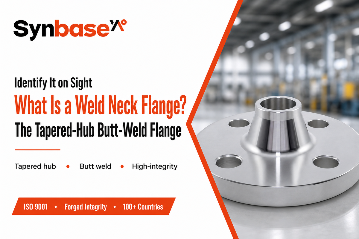
A weld neck flange is a type of pipe flange with a long, tapered neck (the hub) that extends from the flange face down to the wall thickness of the pipe. That pipe is butt-welded to the small end of the hub, so the flange and pipe become one leak-proof, continuous pressure boundary.
Because the weld sits away from the flange face and the hub gradually steps the metal down to pipe-wall thickness, the joint carries pressure, temperature, and bending load without the stress crowding that troubles flatter flange types. In practice the payoff is measurable: a Class 600 carbon steel weld neck flange holds about 1480 psig at 100°F, and because the hub bore is matched to the pipe schedule, the joint avoids the step at the weld root that causes many flange leaks. Get that bore-to-schedule match wrong, though, and even a correctly rated flange can fail where it is welded.
It goes by a few names. On drawings and in catalogs you’ll see it written as a welding neck flange, abbreviated WN, or, when combined with a raised face, an RFWN. Some suppliers call the tall-hub version a tapered-hub or high-hub flange. They’re the same family of fitting.
A weld neck flange is also called a welding neck flange, a WN flange, an RFWN (raised-face weld neck) when it carries a raised face, or a tapered-hub / high-hub flange. Its taller one-piece variant made for vessel nozzles is the long weld neck or nozzle flange, which ASME B16.5 lists under §2.8 as a “straight hub welding flange.”
Key takeaway: if a print calls out WN, welding neck, or RFWN, it’s asking for the same butt-weld flange described here.
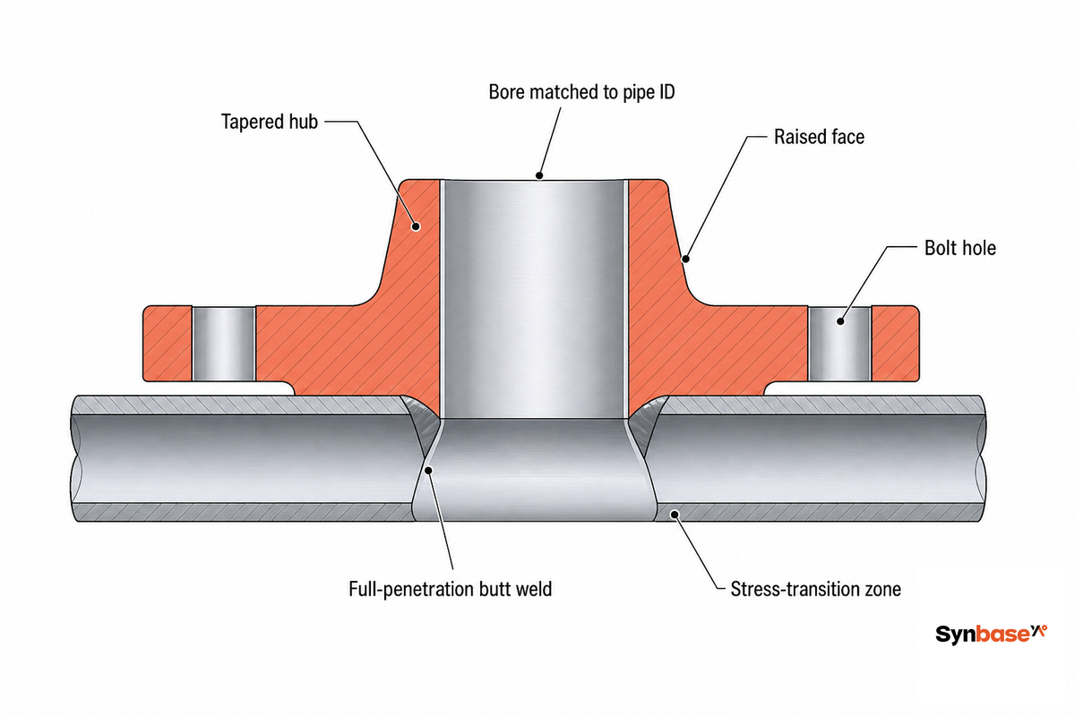
Three design features do the work, and each one earns its keep. What makes a weld neck different is its tapered hub. Why it matters is mechanics: the hub gradually thickens from pipe-wall thickness up to the heavy flange ring, so the bending and pressure stress is spread along the transition instead of concentrating at a sharp shoulder.
So what: that gradual transition is the reason a weld neck survives thermal cycling, vibration, and repeated bending that would fatigue-crack a slip-on at the fillet weld. We call this the Tapered-Hub Stress-Transition Principle: the longer the load has to travel through tapering metal, the lower the peak stress at any one point. Under U.S. federal piping rules (46 CFR 56.30-10), each flange type must stay within its ASME pressure-temperature rating.
Its second feature is bore matching. Its inside diameter is bored to match the inside diameter of the mating pipe, so the bore is set by the pipe schedule, not by the flange class. That matched bore keeps the flow path smooth, which gives a smooth transition, minimizes turbulence and pressure drop, and protects the weld root from erosion. Third comes the butt weld itself: a single V-groove, full-penetration circular weld around the circumference fuses pipe to hub into one wall.
Because the bore follows the pipe schedule, a 6″ Schedule 80 line and a 6″ Schedule 40 line need flanges with different bores even though both are NPS 6, Class 150. Order a weld neck flange against a pipe schedule, never against the nominal size alone, since a bore mismatch leaves a step at the weld root that disturbs flow and concentrates stress.
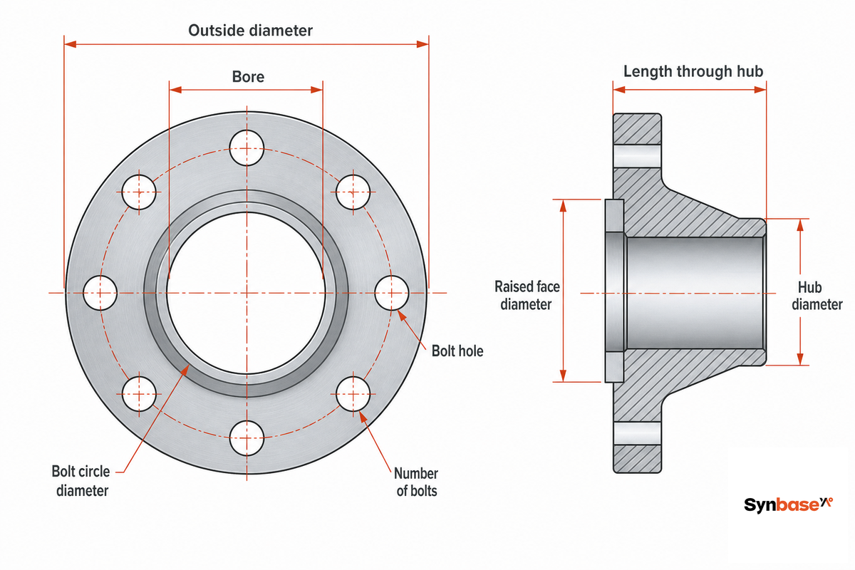
Weld neck flange dimensions are fixed by ASME B16.5 for sizes NPS ½″ through 24″; above that, NPS 26″ to 60″ falls under ASME B16.47 (Series A and Series B). A B16.5 dimension table is read by NPS and class: it gives the outside diameter, flange thickness, hub diameter, length through the hub, bolt-circle diameter, and bolting. Its bore column is the exception, it’s derived from the pipe schedule, so it’s left to the order. One scope limit catches people out: B16.5 doesn’t offer every class at every size. Classes 150 through 1500 run the full NPS ½″–24″ range, but Class 2500 is published only through NPS 12″ — for larger high-pressure joints the design moves to ASME B16.47 or a special.
| NPS | OD | Thickness | Hub OD | Length thru hub | Bolt circle | Bolts |
|---|---|---|---|---|---|---|
| ½″ | 90 | 9.6 | 30 | 46 | 60.3 | 4 × ½″ |
| 1″ | 110 | 12.7 | 49 | 54 | 79.4 | 4 × ½″ |
| 2″ | 150 | 17.5 | 78 | 62 | 120.7 | 4 × ⅝″ |
| 4″ | 230 | 22.3 | 135 | 75 | 190.5 | 8 × ⅝″ |
| 6″ | 280 | 23.9 | 192 | 87 | 241.3 | 8 × ¾″ |
| 8″ | 345 | 27.0 | 246 | 100 | 298.5 | 8 × ¾″ |
| 12″ | 485 | 30.2 | 365 | 113 | 431.8 | 12 × ⅞″ |
| 16″ | 595 | 35.0 | 457 | 125 | 539.8 | 16 × 1″ |
| 24″ | 815 | 46.1 | 663 | 151 | 749.3 | 20 × 1¼″ |
Dimensions per ASME B16.5 Class 150; bore is set by pipe schedule. Higher classes use the same outside-diameter family with thicker rings and longer hubs.
A long weld neck (LWN), or nozzle flange, keeps the same flange face and bolting as a standard weld neck but carries a much taller straight hub, often with a square-cut end rather than a weld bevel, so it can replace a flange-plus-pipe-stub combination on a pressure vessel.
ASME B16.5 §2.8 covers it as a straight hub welding flange and leaves hub length and barrel thickness to the application, because nozzles are sized to the vessel’s pressure, temperature, and reinforcement needs rather than to a fixed table.
Key takeaway: use a B16.5 table to fix face and bolting dimensions, but always confirm the bore against your pipe schedule before ordering.
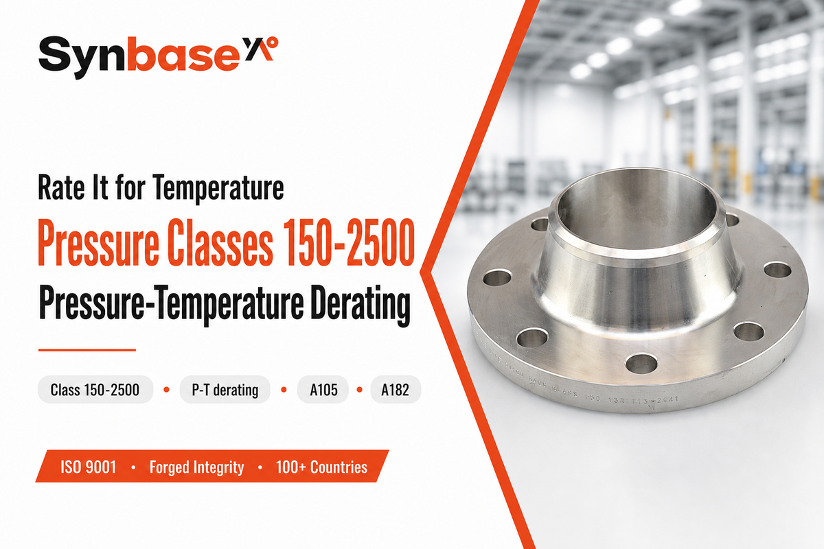
The flange class, 150, 300, 600, 900, 1500, or 2500, is a rating index, not a pressure in psi. Actual working pressure depends on its class, its material, and the operating temperature, and it drops as temperature rises. Reading “Class 150” as “150 psi” is documented as the number-one flange selection mistake, and it cuts both ways: at ambient temperature a Class 150 carbon flange holds far more than 150 psi, while at high temperature it holds far less.
The table below, the Pressure-Temperature Derating Ladder, gives the maximum working pressure (psig) for ASME B16.5 Group 1.1 material, which includes A105 carbon steel, across the temperature range. It’s the single most useful number set in flange selection, and it’s exactly what most product pages omit.
| Temperature | Class 150 | Class 300 | Class 600 |
|---|---|---|---|
| 100°F | 285 | 740 | 1480 |
| 200°F | 260 | 680 | 1360 |
| 300°F | 230 | 655 | 1310 |
| 400°F | 200 | 635 | 1265 |
| 500°F | 170 | 600 | 1200 |
| 600°F | 140 | 550 | 1095 |
| 650°F | 125 | 535 | 1065 |
| 700°F | 110 | 535 | 1065 |
| 750°F | 95 | 505 | 1010 |
| 800°F | 80 | 410 | 825 |
Maximum working pressure for Group 1.1 material (A105) per ASME/ANSI B16.5 pressure-temperature ratings. Carbon steel is limited to roughly 800°F; alloy grades extend higher.
Suppose you’ve a 200 psig process line running at 400°F. Read down the ladder: a Class 150 A105 weld neck flange is rated exactly 200 psig at 400°F, you would be sitting right on the limit with zero margin. Step up to Class 300, which holds 635 psig at that same temperature, and you’ve a comfortable safety factor. This is why temperature, not just line pressure, decides the class.
A U.S. Department of Energy evaluation of B16.5 bolting and flanges notes that some large weld neck flanges derate all the way to a zero maximum pressure rating at the top of their temperature band, a 24″ Class 400 flange is one example. Never assume a flange keeps a usable rating just because it carries a high class number; always read it at your actual temperature.
Key takeaway: pick the class from the derating ladder at your operating temperature, then confirm the material group, not the other way around.
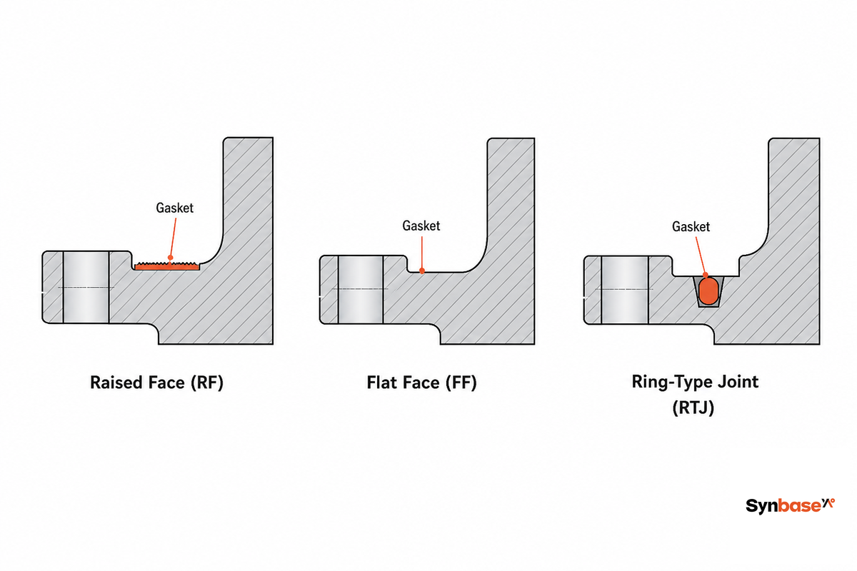
Each flange face is the sealing surface that seats the gasket that meets the gasket, and a weld neck flange is available in three. Whichever face you choose has to match the gasket, the pressure class, and the mating flange, a mismatch here’s a leak waiting to happen. Under U.S. federal piping rules (46 CFR 56.30-10), each flange type must stay within its ASME pressure-temperature rating.
| Face type | Gasket | Typical class range | Where it is used |
|---|---|---|---|
| Raised Face (RF) | Flat ring or spiral-wound | 150 to 400 (the default) | General process, oil and gas, water |
| Flat Face (FF) | Full-face soft gasket | Low pressure | Cast-iron equipment, FRP, pumps |
| Ring-Type Joint (RTJ) | Metal ring (octagonal/oval) | 600 and above | High pressure, sour service, wellheads (API 6A) |
On an RF flange the sealing surface stands proud of the bolting circle, about 1.6 mm (1/16″) on Class 150 and 300, and about 6.4 mm (1/4″) from Class 400 up, so the bolt load concentrates the gasket stress in a narrow band for a tight seal. RTJ goes further: a hardened metal ring is crushed into machined grooves on both flanges, giving the metal-to-metal seal that high-pressure and sour-gas service demand. For most process lines, though, a raised face weld neck flange with a spiral-wound gasket is the workhorse, and the costliest mistake here is bolting that raised face to a flat-face cast-iron part, which can crack the casting.
Never bolt a raised-face flange against a flat-face cast-iron part. The raised face point-loads the brittle cast iron as the bolts pull up, and the cast flange can crack. When you mate to cast-iron equipment, use a flat-face weld neck (or a full-face gasket) so the load spreads evenly.
Key takeaway: RF for most process service, FF only when mating to cast iron or fiberglass, RTJ from Class 600 up and on anything sour or wellhead.
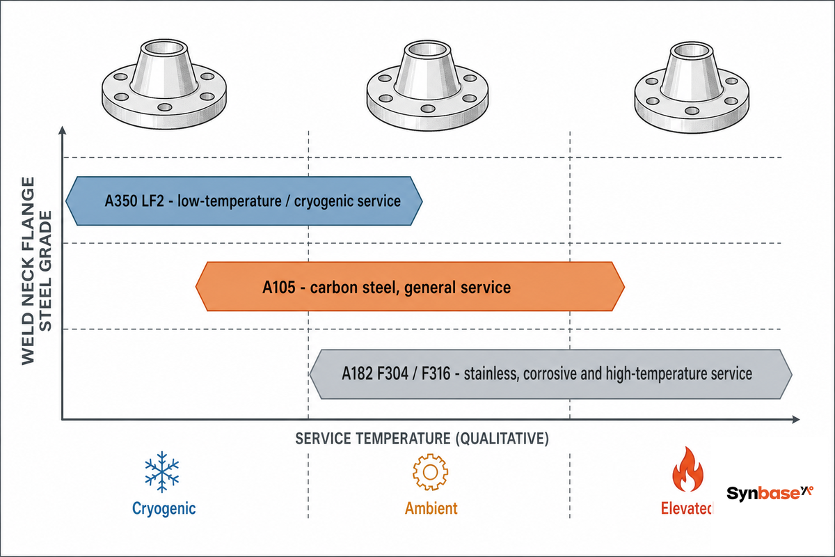
A weld neck flange is only as good as the steel it is forged from, and the grade has to be suitable for the service environment, temperature, corrosion, and whether the line ever goes sub-zero. Three ASTM specifications cover the great majority of flanges.
| Grade | Type | Service envelope | Use it for |
|---|---|---|---|
| ASTM A105 | Carbon steel (forged) | −29°C to ~427°C (to ~800°F) | General oil, gas, water, steam |
| ASTM A350 LF2 | Low-temp carbon (impact tested) | Charpy tested at −46°C (−50°F) | Cold climates, LNG, cryogenic |
| ASTM A182 F304/F316 | Stainless steel | Corrosive and elevated-temperature | Chemical processing, pharma, food, marine |
| ASTM A182 F11/F22 | Chrome-moly alloy | High temperature / pressure | Power plant steam, turbines, refinery hot lines |
One dividing line most buyers miss is at the cold end. A105 carbon steel is rated to a minimum of −29°C (−20°F) without impact testing; below that, the steel can turn brittle, so the standard moves you to A350 LF2, which is Charpy-impact tested at −46°C (−50°F) and carries a minimum yield around 250 MPa (36 ksi). This is also where the forming route matter: a forged one-piece flange, the only construction ASME B16.5 recognizes for pressure-boundary weld necks, has a grain flow that follows the stress path around the hub, where a flange machined from flat plate cuts across that grain. For Synbase Steel, which forges rather than cuts its flanges, that grain continuity is the reason the forming route is specified, not an afterthought.
Key takeaway: A105 for general carbon service, A350 LF2 once the line goes below −29°C, A182 stainless or chrome-moly for corrosion or high heat; a stainless steel weld neck flange in F316 is the default for corrosive chemical service.
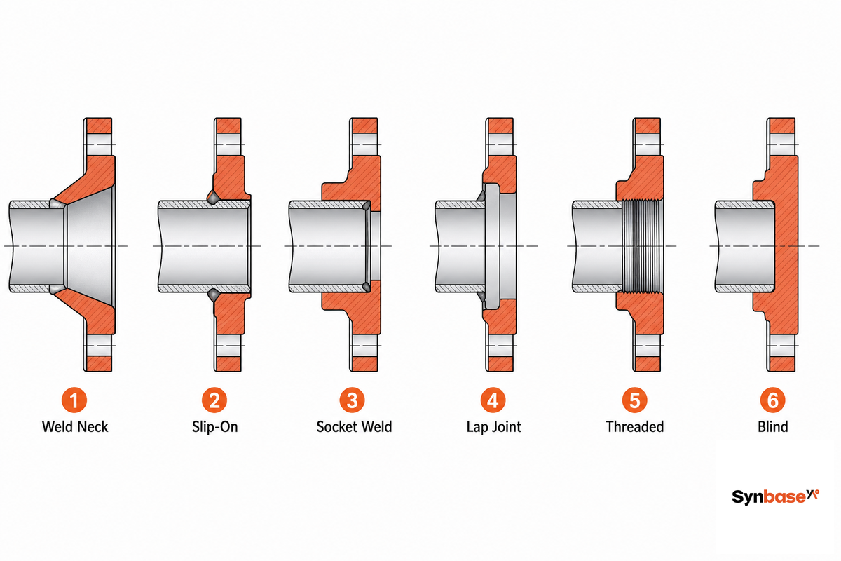
A weld neck is the strongest common flange, but “strongest” and “right” aren’t the same word. Honestly, the best type of flange depends on pressure, temperature, cost, and how the line is built. The table below, the 6-Type Flange Connection Spectrum, lines up the weld neck against every alternative you’re likely to consider, covering the common weld neck flange types and their siblings side by side. Under U.S. federal piping rules (46 CFR 56.30-10), each flange type must stay within its ASME pressure-temperature rating.
| Flange type | Connection | Pressure / temp suitability | Fully RT-inspectable? | Typical service |
|---|---|---|---|---|
| Weld Neck (WN) | Single butt weld to pipe | Highest; cyclic and severe | Yes (100%) | Critical, high-pressure lines |
| Long Weld Neck (LWN) | Integral hub, butt weld | Highest; vessel nozzles | Yes | Pressure-vessel and tank nozzles |
| Slip-On (SO) | Slides over pipe, two fillet welds | Low to moderate | No (fillet welds) | Low-pressure straight-run pipe |
| Socket-Weld (SW) | Pipe seats in socket, fillet weld | High, small bore only | Limited | Small-bore high-pressure lines |
| Lap-Joint (LJ) | Loose ring over a stub end | Low to moderate | N/A | Lined pipe, frequent dismantling |
| Threaded | Screwed, no weld | Low; no-weld areas | N/A | Utility, hazardous no-hot-work zones |
| Blind | Solid disc, no bore | Matches class | N/A | Isolation, line terminations |
| Reducing Weld Neck | Butt weld, two bore sizes | High | Yes | Size transitions on pressure lines |
| Orifice | Weld neck with tappings | Per class | Yes | In-line flow metering |
Weld neck and slip-on flanges differ in the weld and what it buys you. Weld necks are joined to the pipe by one full-penetration butt weld that can be 100% radiographed; a slip-on slides over the pipe and is held by two fillet welds that can’t.
They therefore withstand and handle higher pressure, higher temperature, and fatigue far better. The slip-on is cheaper, easier to align on straight-run pipe, and forgiving of small cut-length errors. Piping references commonly put a slip-on at roughly two-thirds of a weld neck’s internal-pressure strength and about one-third of its fatigue life, ample for a low-pressure water header, not enough for a cyclic gas line.
A field thread on Eng-Tips captures the practical version well: experienced piping engineers reach for weld necks at fittings where bolting clearance matters, and accept slip-ons on plain straight-run pipe. They earn their premium where the service is severe, not on every joint.
Key takeaway: default to a weld neck for severe or cyclic service; spend the saving on a slip-on only where pressure, temperature, and fatigue are all mild.
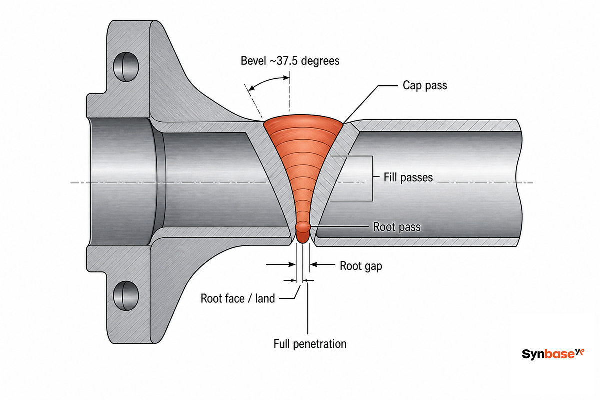
Installing a weld neck flange is a butt-welding job, and the quality of that single weld is the quality of the joint. Both the pipe end and the flange hub carry a weld bevel, typically a 37.5° included-angle V groove with a small root face, so that when they’re fitted together with a controlled root gap, the welder can lay a full-penetration weld from root to cap.
This sequence is straightforward but unforgiving: bevel and clean the pipe end to match the hub, insert and align the flange face square to the mating flange (alignment tools or tack welds hold it), then run the root and fill passes per a qualified welding procedure (WPS) under ASME BPVC Section IX. Because the finished weld is a single butt joint in open pipe, it can be examined by 100% radiographic (RT) testing per ASME BPVC Section V, the verification that a slip-on’s buried fillet welds simply can’t receive.
Perfect welds are necessary but not sufficient, though. Once the flange is bolted up, leak-tightness is governed by the bolted joint itself, gasket choice, bolt-tightening sequence and load, and the qualification of the person assembling it. ASME PCC-1 treats this pressure-boundary bolted flange joint assembly as its own discipline, and a large share of in-service flange leaks trace back to assembly practice rather than the weld. Spec the weld neck, then assemble the joint to a procedure.
“Misalignment is the quiet defect. A weld neck that’s tacked up a degree or two out of square will pass a visual check, then show incomplete root fusion on the film, and a rejected radiograph at a flange means cutting it out and starting over.”
— Synbase Steel forging and inspection team
Weld neck flanges are joined by arc welding, usually TIG (GTAW) for the root pass and MIG or stick for fill, laying a single full-penetration butt weld in the V groove between the pipe bevel and the hub bevel. That weld is run to a qualified WPS, then inspected; on critical lines it’s 100% radiographed to confirm penetration and the absence of porosity or lack-of-fusion.
Key takeaway: the value of a weld neck is unlocked only by a full-penetration weld and the inspection it allow, skimp on either and you’ve paid for strength you can’t prove.
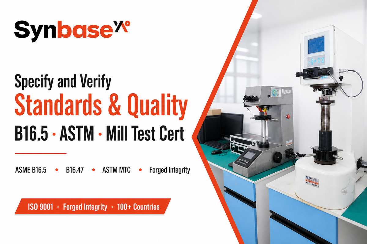
A weld neck flange lives inside a stack of standards, and a clean purchase order names all of them. ASME B16.5 governs dimensions and pressure-temperature ratings through NPS 24″; ASME B16.47 takes over for NPS 26″ to 60″. Its current edition is ASME B16.5-2025 (released 30 May 2025), which replaced the 2020 edition, corrected an N08800 material-classification error, and expanded the nickel and duplex temperature data out to −29°C to 815°C. Specify the 2025 edition on new work so you inherit those corrections.
On the material side, the ASTM grade (A105, A350 LF2, A182) sets the chemistry and mechanicals, and a Mill Test Certificate (MTC) to EN 10204 3.1 ties the actual heat of steel to your order. One common documentation failure in receiving is accepting a flange whose MTC cannot be traced to a heat number stamped on the part. Two further points sharpen a spec. ASTM material standards are themselves live documents, A105, A182, and A350 all carry 2026 editions, so cite the current year rather than a dated copy. And in regulated VOC service, every flange is a monitored connector under EPA leak-detection-and-repair (LDAR) rules (40 CFR 60.481a), which can tilt the choice toward a fully welded weld neck wherever fugitive-emission monitoring is in play.
For buyers who want the commercial side, stock sizes, materials, and a quote, our weld neck flange supplier page lists forged A105 and stainless options against this same checklist, and the broader pipe flanges range covers the matching slip-on, blind, and socket-weld types.
Key takeaway: a complete weld neck flange spec line names size-and-schedule, class, face, grade, standard edition, and testing, leave any one out and you’ve left it to the supplier.
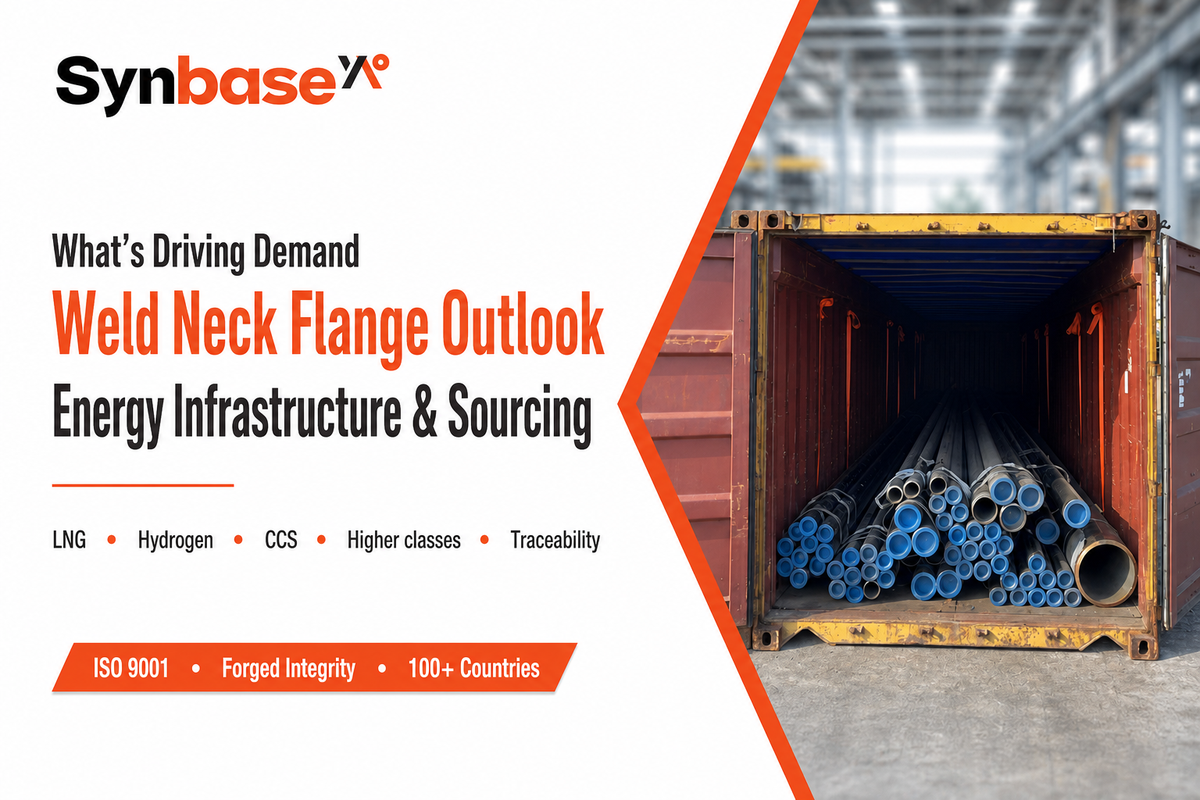
The force pulling weld neck demand in 2026 is the gas build-out specifically, not energy across the board. It’s worth being precise here: the U.S. Energy Information Administration’s mid-2026 outlook has global oil demand actually easing by about 1.1 million barrels per day, even as U.S. LNG exports climb from 15.1 to 17.2 Bcf/d. So the weld neck story rides gas, LNG, and hydrogen infrastructure, not oil consumption. As LNG terminals and the first wave of hydrogen-ready pipelines move from drawing board to procurement, the duty is shifting toward higher pressure classes and tighter material traceability, and the weld neck is the only butt-weld flange rated for that cyclic, high-pressure service, which is why it holds the largest share of the flange market. Hydrogen in particular raises the bar: it demands documented material control and leak-tight metal seals, pushing specifications toward RTJ faces and impact-tested or stainless grades rather than the cheapest carbon option.
Standards are moving in step. Arrival of ASME B16.5-2025 (May 2025) tightened material data and sealing requirements, so a flange specified to the 2020 edition is already a half-step behind. Inspection is changing too: recent USPTO filings describe automated, AI-based flange-integrity classification from weld images, a sign that the radiographic record buyers demand today is heading toward digital, image-classified quality data tomorrow.
For context, the global flange market is often put near USD 6.4 billion in 2025 with mid-single-digit annual growth through the next decade; treat those figures as directional background rather than a buying signal. One signal matters more, and it is narrower: if you’re planning a high-pressure or hydrogen-ready line for 2026 startup, specify forged weld neck flanges to ASME B16.5-2025, with the right class read off the derating ladder, RTJ faces where the service is sour or above Class 600, and a full MTC and RT record, the documentation that those projects are now rejecting shipments for. Picture a buyer specifying a long weld neck flange for a 2026 hydrogen header to the older 2020 edition: the submittal risks rejection, because the 2025 revision tightened the very sealing and material rules that hydrogen service leans on.
Key takeaway: the demand story is energy infrastructure, not a market-size chart; build new high-pressure lines around the 2025 standard, forged construction, and traceable testing.
Need forged weld neck flanges to ASME B16.5-2025, with full MTC and RT documentation?
We wrote this weld neck flange guide to put the dimensions, the pressure-temperature derating numbers, and the type-by-type selection logic in one place, because most references give you only one piece at a time. Our pressure ratings are drawn from ASME B16.5 Group 1.1 data and U.S. federal flange references; the selection trade-offs reflect how forged-flange engineers actually specify these parts at order review. Reviewed by the Synbase Steel technical team.
Synbase Steel supplies steel pipe, fittings, flanges, valves and OCTG for oil and gas, petrochemical, power, water and industrial projects. Our technical guides are written to help buyers compare standards, grades, dimensions, coatings, inspection requirements and commercial terms before sending an RFQ.
We focus on practical specification work: matching pipe process to service conditions, checking wall thickness and end finish, reviewing MTC and NDT requirements, and clarifying documentation before production or shipment.
Project support across seamless pipe, ERW, LSAW, SSAW, buttweld fittings, forged flanges, valves and oilfield tubulars.
Specification review for ASTM, ASME, API, EN and DIN standards, including material grade, pressure class, coating and inspection scope.