Send Your RFQ to Synbase Steel
Prefer to send drawings, BOMs or attachment lists by email? sales@synbasesteel.com

A field guide to flange connection, face, and class – by the Synbase Steel forged-flange team. (Updated June 2026)
Flange types you meet in a piping system are not a single list, but rather three overlapping questions: how the flange attaches to the pipe (connection), how it seals against the mating flange (face), and how much pressure and temperature it’s built to withstand (class). Get one of those three wrong and you can bolt two pipe, valve, pump, or nozzle flanges together, and it’ll still weep under pressure. This guide pull those three apart, and covers the many types of flanges – six common styles plus their specialty siblings – to give you a repeatable method for specifying the different types of pipe flanges that connect piping in oil and gas, water, or process applications.
| Defining axes | Connection × Face × Pressure class |
| Main connection types (ASME B16.5) | Weld neck, slip-on, socket weld, threaded, lap joint, blind |
| Face types | Raised face (RF), flat face (FF), ring-type joint (RTJ) |
| Pressure classes | 150, 300, 400, 600, 900, 1500, 2500 (Class 2500 only to NPS 12) |
| Size split | ASME B16.5 = NPS 1/2–24; ASME B16.47 = NPS 26–60 |
| Governing edition | ASME B16.5-2025 (mandatory from Jan 1 2026) |
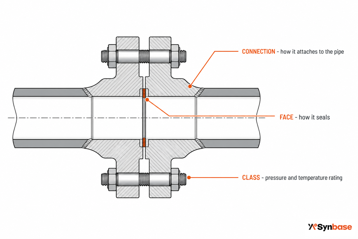
In essence, a flange is a ring or plate that mechanically couples either two lengths of pipe, a pipe to a pump, valve, vessel nozzle, or similar piece of equipment. Its purpose is to hold a pair of pipe ends or equipment to be joined to accommodate a seal and bolt material in order to establish a leak-free piping seal which can, over the useful life of the equipment, be separated for inspection or repair. Although there are several different pipe fitting classifications of which to be aware when considering flanged pipes or other mechanical couplings such as welded pipes and fittings that are threaded, it wouldn’t be prudent to specify only one type of flange.
Use what we call the Three-Question Flange Type Test. Every flange answers three independent questions, and a complete specification names all three:
Europeans made this simple, with a code system: for EN 1092-1 type flange the type is indicated by type number like EN 1092-1 Type 11B / DN150 / PN16; where 11 indicates the Connection Type, the ‘B’ indicates the flange face, the DN150 indicates the Nominal Size of the flange (mm) and finally PN16 indicates the pressure class. This three-dimension selection process applies equally well to the North American standard flanges defined in ASME B16.5. Synbase manufactures a full range of forged steel pipe flanges to both ASME and EN standards.
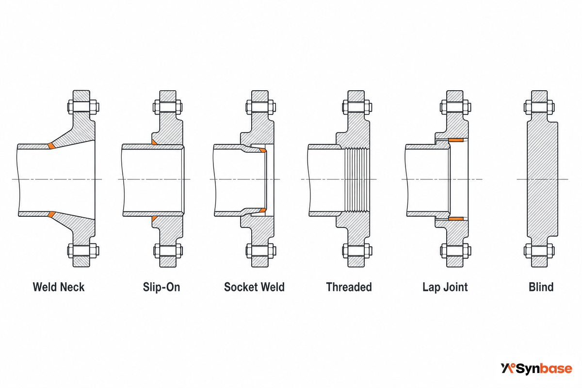
ASME B16.5 recognizes six basic flange types: weld neck, slip-on, socket weld, threaded, lap joint and blind; the differences lie in the connection type to the pipe, pressure capacity and fatigue life. selection begins with service severity, then connections, then cost. The weld neck, slip-on, and socket weld (the first three) are hubbed flanges; threaded, lap joint, and blind (the latter three) are not. the slip-on’s loose ring is sometimes called a backing flange, while the socket weld in this group is generally found on small-diameter service. Never substitute the cheaper slip-on for the weld neck as a drop-in: a flange’s design and geometry, not its bolt holes, set how it meets the pipe end, and that geometry alone accounts for the numbers shown below.
| Flange type | How it attaches | Strength vs. weld neck | Best-fit service | Typical face |
|---|---|---|---|---|
| Weld neck (WN) | Tapered hub, single full-penetration butt weld | Baseline (100%) | High pressure/temperature, cyclic, critical lines | RF, RTJ |
| Socket weld (SW) | Pipe seats in a socket, one fillet weld | +50% fatigue vs slip-on | Small-bore, high-pressure, instrument lines | RF |
| Slip-on (SO) | Slides over pipe, two fillet welds | ~67% pressure, ~33% fatigue | Moderate pressure, non-cyclic, easy alignment | FF, RF |
| Threaded (TH) | NPT thread, no welding | Lower (no strength weld) | Small-bore, low-pressure, no-hot-work areas | FF, RF |
| Lap joint (LJ) | Loose ring over a butt-welded stub end | ~10% fatigue life | Frequent dismantling; alloy stub + cheap backing | Stub-end face |
| Blind (BL) | Solid disc, bolted closure | Highest bending stress (static) | Line ends, manways, unused nozzles | FF, RF, RTJ |
| Long weld neck (LWN) | Extended hub, butt weld | ≈ weld neck | Vessel/nozzle barrels, high pressure | RF, RTJ |
| Orifice | Tapped pair with jack screws | Per base type | In-line flow metering | RF |
| Reducing | One part steps two line sizes | Per base type | Size transitions | RF, FF |
| Spectacle blind | Figure-8 plate between flanges | n/a (isolation) | Positive, visible line isolation | RF, RTJ |
Approximate Strength/Fatigue Relative Numbers. Information adapted from published engineering resources based on B31.3 and PD 5500 practice.
Those ratio differences translate to money. Engineering references-which translate the type-agnostic B16.5 pressure ratings to stress-related factors using ASME B31.3 and PD 5500 data-show a slip-on with about 2/3 the pressure strength of a double-welded weld neck and 1/3 the fatigue life of that weld neck; the lap joint’s fatigue life is 1/10. The socket weld flange has about the same static pressure strength as the slip-on but about 50% more fatigue strength at roughly 10% more cost. Use the slip-on in non-cycling applications and pay for the weld neck in critical areas.
If you come across listings of 5, 6, 9, 13, or even 16 different “types” of flanges, don’t panic-they just mean different things. ASME B16.5 has just six standard types of pipe flanges (connection types), as described in the table above. Add the plate flange and most lists hit 7-9 types. Beyond that, you find specialty types, like orifice, reducing, expander, long weld neck or spectacle blind, and listings by face or material. In short, there are just six basic connection types, and all the others fall into sub-types and specialty designs.
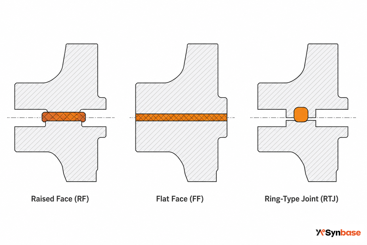
Flange face is the second dimension, determining which gasket seals the line. You’ll typically find raised face (RF), flat face (FF) and ring joint (RTJ) designs in steel line applications, and you can’t swap one design for another.
| Face | Seal mechanism | Typical class band | Not for |
|---|---|---|---|
| Flat Face (FF) | Full-face soft gasket | 150–300 | High-pressure steel lines |
| Raised Face (RF) | Concentrated soft gasket | 150–2500 | Brittle cast-iron mating |
| Ring-Type Joint (RTJ) | Metal ring, plastic deformation | 600–2500, API 6A | Low-pressure / FF mating |
A less obvious fact is that the raised face design comes in two sizes. Depending on the flange pressure Class, the “lip” is either raised 1/16-inch (for Classes 150 and 300) or 1/4-inch (Classes 400 and above), and and many dimension charts include that raised-face height for Class 150/300 but exclude it for Class 400 and above. The gasket-seating surface itself is specified to a 125-250 microinch Ra finish so it grips the gasket. These face geometries and finishes are all standardized in ASME B16.5. An RTJ metal ring seals to about 6,250 psi for the common Style R, sits in a groove roughly 5 mm deep, and is single-use – replaced on 100% of disassemblies.
Never bolt a raised-face flange to a flat-face flange. Because the contact is off-set, a bending moment can crack the more brittle flat-face casting; ASME B31.1 requires the raised face to be machined off and a full-face gasket used when joining cast iron to a carbon-steel flange. RF and RTJ are equally non-interchangeable: the RTJ groove is deeper, so bolts sized for an RF flange come out too short and silently under-bolt the joint.
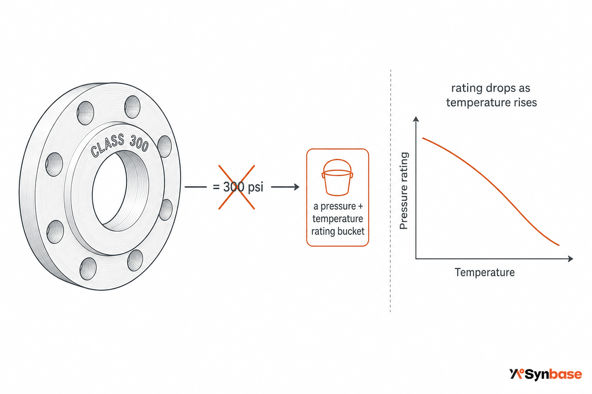
Class numbers A flange class number is an overall pressure/temperature rating bucket, not the psi a connection operate at. This is by far the number one misunderstanding regarding flanged connections, so front-loading it: reading a “Class 300” flange as “300 psi” will either under-buy or over-pay for the joint. Spec too low and the joint can fail hydrotest; spec too high and you pay for a heavier forging the line never needed – field practitioners report both errors on the same project when the class-versus-psi rule is not understood.
Take an example, work end to end.
An ASTM A105 carbon steel (material Group 1.1) Class 600 flange is rated about 1,480 psig @100°F – not 600 psi – at the lower end of the temperature range, and that rating derates with increasing temperature to about 825 psig @800°F as the steel loses strength. Lower the class and the pattern repeats: Class 150 is 285 psig @100°F, Class 300 is 740 psig. A class number only resembles its psig rating toward the high end of the temperature range; run your own number against the ASME B16.5 pressure-temperature rating lookup before you finalize the design.
Limitation This can slip through unnoticed. Not all class ratings exist in all pipe sizes. For example, Class 2500 is limited to pipe sizes 12-in and under according to ASME B16.5, while lower classes can be sourced across the entire range of B16.5 sizes, 1/2 to 24-in.
Regardless of brand, flange dimensions and the bolt pattern are fixed by flange class and pipe size, so the flange size, end bore, and face for a 6-in Class 300 land on the same bolt circle across multiple vendors. Beyond 24-in, flanges are standardized according to ASME B16.47, which covers flanges through 60-in with top-end ratings of Class 900, proving that bigger doesn’t necessarily mean higher class.
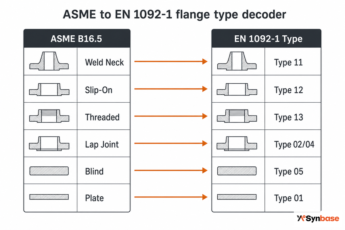
When a European or Asian drawing calls out a “Type 11” or “Type 01” flange, it’s using EN 1092-1’s numeric type numbers – and “Type 11” is the weld-neck flange, not “Type 1.” Most “types of flanges” guides go silent at this point, and it’s exactly here that a mismatch slips through unnoticed and turns into a non-mating joint on site.
Below is a quick chart of the flange types you’re most likely accustomed to, compared against their European counterparts, where the ASME side is standardized in ASME B16.5:
| Connection | ASME B16.5 | EN 1092-1 type | Pressure designation |
|---|---|---|---|
| Weld neck | WN | Type 11 | PN 2,5–PN 400 / Class 150–2500 |
| Slip-on (welding) | SO | Type 12 | PN designation |
| Plate (slip-on plate) | — / plate | Type 01 | PN designation |
| Threaded | TH | Type 13 | PN designation |
| Lap joint (loose) | LJ | Type 02 / 04 (+ collar) | PN designation |
| Blind | BL | Type 05 | PN designation |
EN 1092-1 also uses face codes that correspond to the ASME designations, with Form “B” equivalent to an RF (raised face) and Form “A” equivalent to an FF (flat face).
The weld-neck is the equivalent of ASME ‘Weld Neck’(often referenced as a long hub and type ‘A’), but has an EN 1092-1 designation of Type 11 and ranges from PN 2,5 to PN 400 for every size available within the standard. A ‘11’is simply the type of flange – it isn’t tied to a specific size or pressure and has a PN number, similar to an asme class number, that dictates operating parameters, and decreases at elevated temperatures.
Here the trap is mechanical, not nominal. An ASME B16.5 flange and an EN 1092-1 flange of the same nominal size and rating still have different bolt-circle diameters and bolt counts, so they won’t bolt together or seal– connecting the two systems requires a transition spool with one ASME and one EN flange. Field crews learn this the hard way: a fabricator receives European “Type 11” flanges for an ASME line, assumes they bolt up because the size and PN look right, then finds on site that the bolt circles do not match and loses a shift sourcing a spool. Confirming the standard – not just the size – on the drawing prevents the delay. A similar warning applies within ASME B16.47: its Series A (MSS SP-44 lineage) and Series B (API 605 lineage) share size and class designations but have different bolt patterns and aren’t interchangeable.
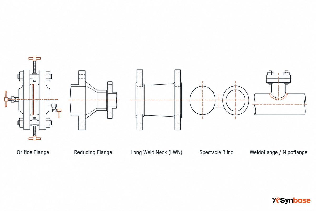
Beyond the six main connection types sit specialty flanges that solve a specific job, and you’ll meet them on real plant drawings even though they rarely appear in beginner lists. A flange is used wherever a line must come apart for service, and different flange needs are met by these special types; industrial flanges are available well beyond the standard six. These are the ones worth recognizing:
This is also where connection technology is moving fastest. Innovation in 2025 included an API 6A hydraulic quick-connect flange that cut make-up time by 75-90%, and a patented bolted-flange joint (USPTO/EPO publication EP3906345A1) that spans the whole interface with a single vacuum-monitored seal – if a bolt fails and the flanges move, the vacuum is lost and an alarm trips. Beyond the common flange types, a custom flange can be forged to a drawing, and socket-weld flanges turn up in specialty small-bore variants too. For the standard catalog, Synbase forges orifice and reducing flanges alongside the six main types.
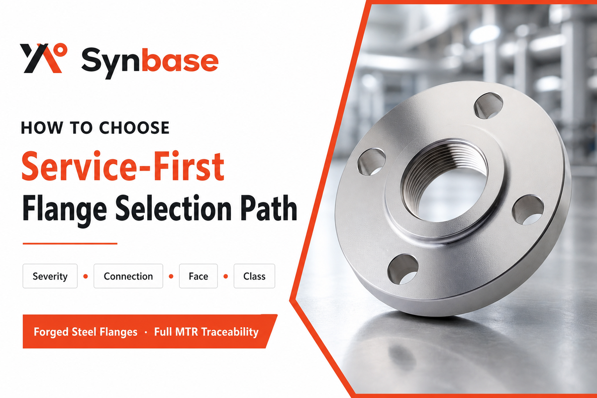
Choose a flange type service-first: let the service severity pick the connection, then the face, then the class – never start from the bolt pattern or the unit price. Run these four steps in order.
Two field rules refine this. First, ASME B16.5 pressure-temperature tables are type-independent: a Class 300 weld neck and Class 300 slip-on of the same grade material enjoy identical static rating, so the practical merits of selecting a weld neck rather than a slip-on lie in its greater fatigue life and the inspectability of its welded joints, not in higher allowable pressure. Second, inspectability and corrosion often trump pressure in selection criteria: slip-on flanges are usually banned in sour service (H2S), as hydrogen can concentrate at the gap between pipe bore and flange face, and the internal fillet weld often can’t be x-rayed. The ASME B31.1 code limits slip-on flanges in this and many applications to Class 300 and NPS 4 using double fillet welds. On one revamp, a team carried slip-on flanges over onto a Class 600 line that now saw thermal cycling; the fillet welds cracked within two years, and re-cutting every joint to weld neck during an unplanned shutdown cost far more than the weld-neck premium would have up front. Let the service, not the existing drawing, pick the type.
One other detail not contained in the “type label”: even correctly selected flange can leak from improper assembly. Indeed, there’s a standard for the sealing-engineering adage: “gaskets don’t fail, bolted flange assemblies leak”-uneven bolt load, poor face finish, or misalignment account for the vast majority of weeps, explaining the existence of ASME PCC-1 for the bolted joint assembly process. There’s no universal “flange leak rate” to reference either: published failure frequencies range from about 5×10⁻⁵ to 2.1×10⁻² per year, a roughly 400× spread across older quantitative-risk datasets. Treat any single quoted rate as dataset-specific, not a constant. For a guided four-question version of this method, use the flange type and face selector.
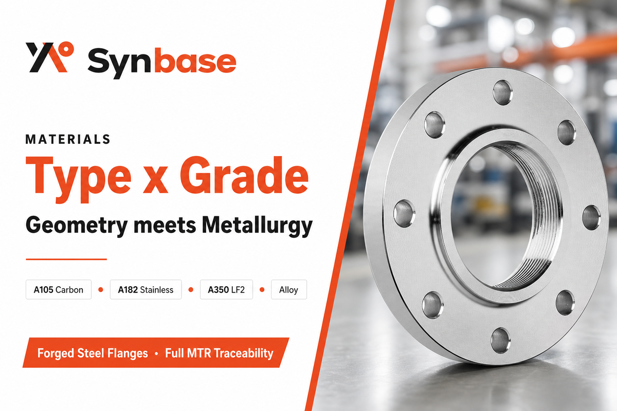
Type and grade, the two critical factors in flange selection, are distinct, the former relating to geometry, the latter to metallurgy, and both must match the service conditions. Common flange materials run a wide range: any of the six standard flange types may be forged from ASTM A105 carbon steel, ASTM A182 F304/F316 stainless, A350 LF2 low-temperature carbon, chrome-moly, duplex, or nickel alloy. grade will govern your maximum operating temperature and your corrosion environment: the British code PD 5500, for instance, allows slip-on flanges only up to about 350°C due to creep, regardless of geometric type. Get the grade wrong against temperature and the failure mode is not slow corrosion but brittle fracture during a cold start-up – a risk field engineers flag on parts nominally rated to -20°F when a standard carbon grade is substituted for a low-temperature A350 LF2. Material selections deserve separate treatment, so see Synbase’s full breakdown of stainless steel flanges (A182) and the grade-to-service map on the main flanges page rather than duplicating it here.
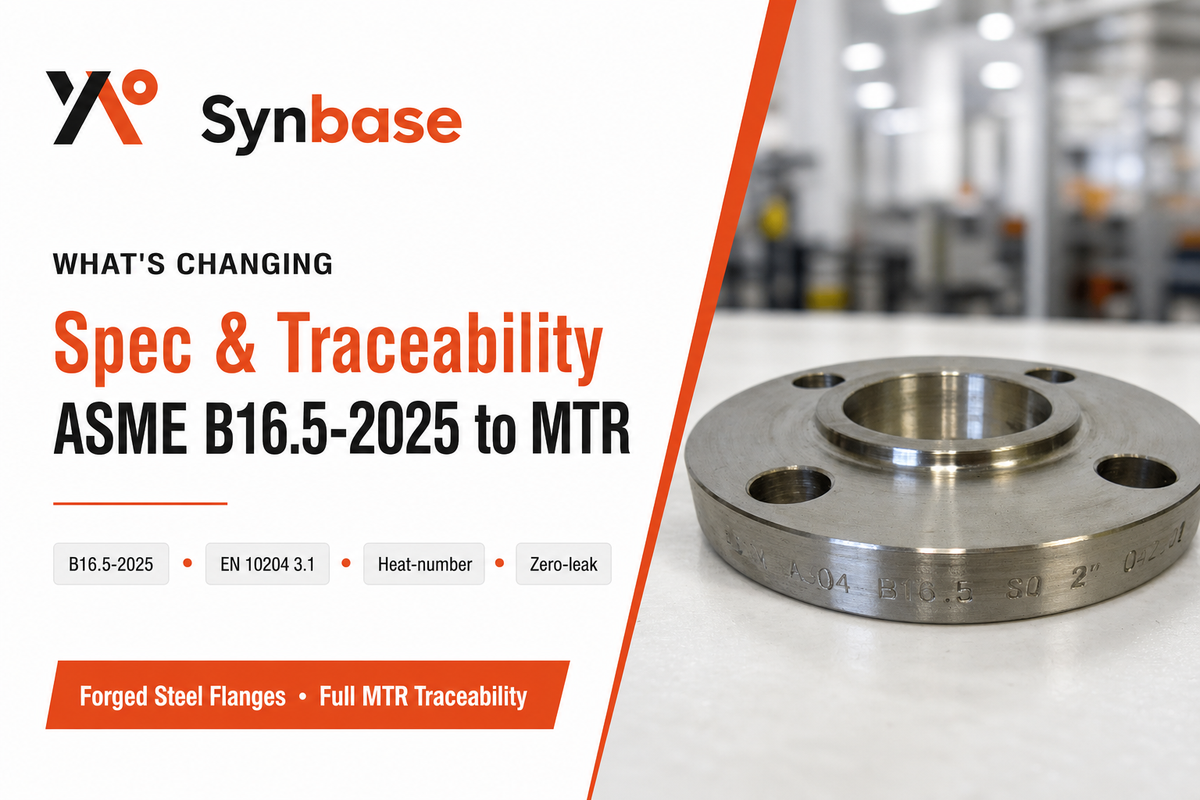
Certainly the most impactful change isn’t market-driven, but based on an updated standard: the ASME B16.5 standard edition 2025 became mandatory January 1, 2026, supplanting the 2020 version and giving projects still under contract a buy-off deadline of June 30, 2026. Revision to ASME B16.5 involves a re-classification of one nickel alloy and a expanded rating range to 29C-815C for all nickel alloys and duplex steels, meaning any type selected should be referenced in its 2025 form, as should the companion large-diameter specification, ASME B16.47 (which also switched to the 2025 edition on the same date). If your current project references the 2020 specification, check the PO to determine which edition to procure. Spec a 2026 line against the 2020 edition out of habit and an inspector can reject the lot on the rating basis alone – the kind of avoidable schedule slip that lands on the buyer, not the mill.
There’s a second shift that’s occurring beyond products: sourcing. Traceability is coming into the type specification itself. As for more critically-service oriented customers, they’re requesting the EN 10204 3.1 mill test certificate on all standard flanges – not just alloys – for full heat-number traceability and MSS SP-25 marking. Sourcing shifts toward direct mill supply, where a complete documentation packet can be provided. Energy-transition lines – such as those supporting hydrogen, carbon capture, offshore wind and LNG applications – are leading the charge for fully-documented, zero-leakage forged flanges. Analysts size the global flanges market at roughly $6.4 billion in 2025, but that figure is background; the shift toward detailed certification and traceability is what will dramatically impact buyers in the market.
“We forge the weld-neck hub rather than cutting it from plate, so the grain flow follows the stress path around the butt weld. On a pressure-boundary flange that is the engineering reason the forming route matters, and it is also why we tie every lot to its heat number from the forging press to the packing list.”
Synbase steel can provide you all 6 common type of flanges,as well as special application type, according to ASME B16.5, B16.47 and EN1092-1 international standards in different material grade including Carbon steel, stainless steel and other special alloy grade with trace of heat number for each batch of the product with EN10204 3.1 certificate before shipment.
Synbase Steel forges pipe flanges to ASME B16.5, ASME B16.47, and EN 1092-1 within E-CHENG STEEL GROUP, so the type, face, and class distinctions in this guide are the same ones we resolve at order review every week, including the cross-standard “Type 11 vs. weld neck” and RF-to-RTJ mismatches that reach us before they reach a job site. Reviewed by the Synbase Steel technical team.
Synbase Steel supplies steel pipe, fittings, flanges, valves and OCTG for oil and gas, petrochemical, power, water and industrial projects. Our technical guides are written to help buyers compare standards, grades, dimensions, coatings, inspection requirements and commercial terms before sending an RFQ.
We focus on practical specification work: matching pipe process to service conditions, checking wall thickness and end finish, reviewing MTC and NDT requirements, and clarifying documentation before production or shipment.
Project support across seamless pipe, ERW, LSAW, SSAW, buttweld fittings, forged flanges, valves and oilfield tubulars.
Specification review for ASTM, ASME, API, EN and DIN standards, including material grade, pressure class, coating and inspection scope.