Send Your RFQ to Synbase Steel
Prefer to send drawings, BOMs or attachment lists by email? sales@synbasesteel.com

Nearly half of the orifice meter run that fail in the field fail because of pressure taps or the wrong pressure class, not the orifice plate! Our pre-machined NPT orifice flanges with matched jack screws have the precision and quality of an orifice run tested to ASME B16.36 standards and come fully tested in tested pairs.
Request a Quote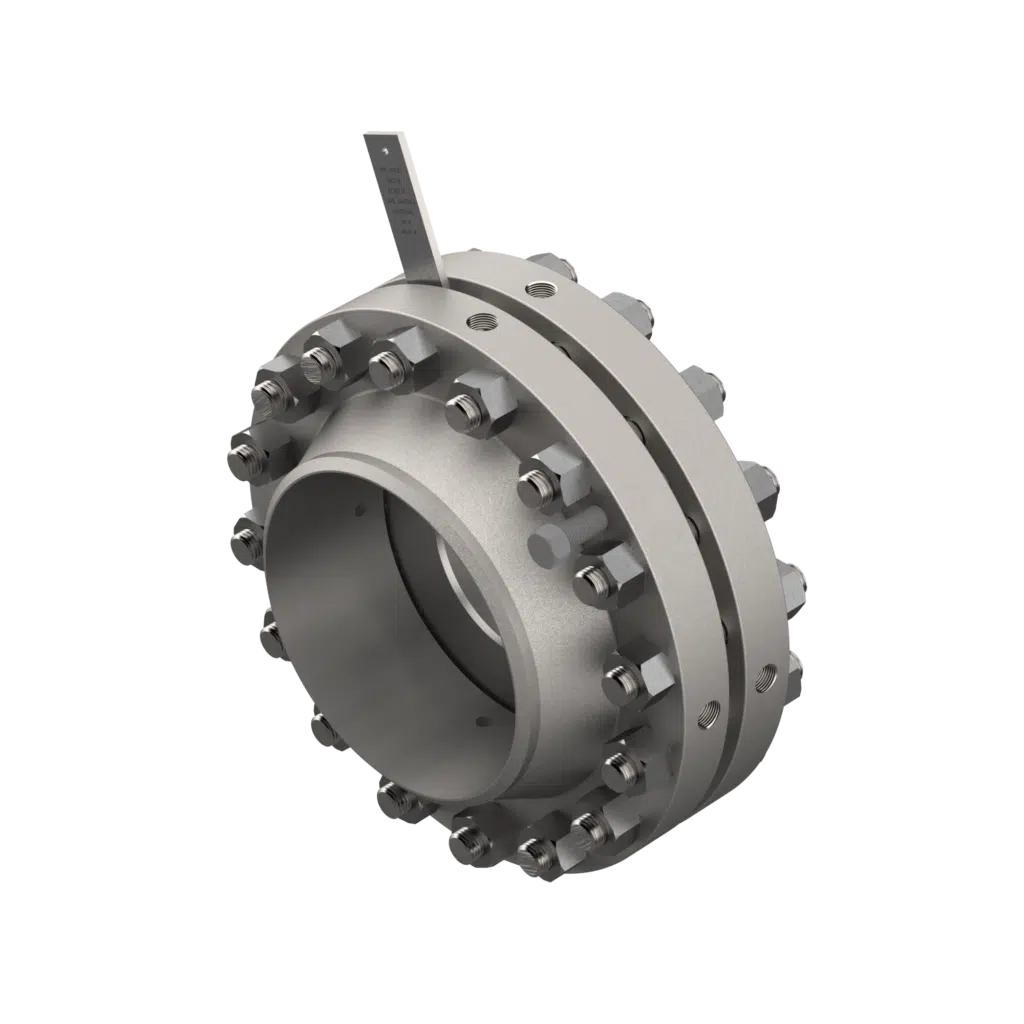
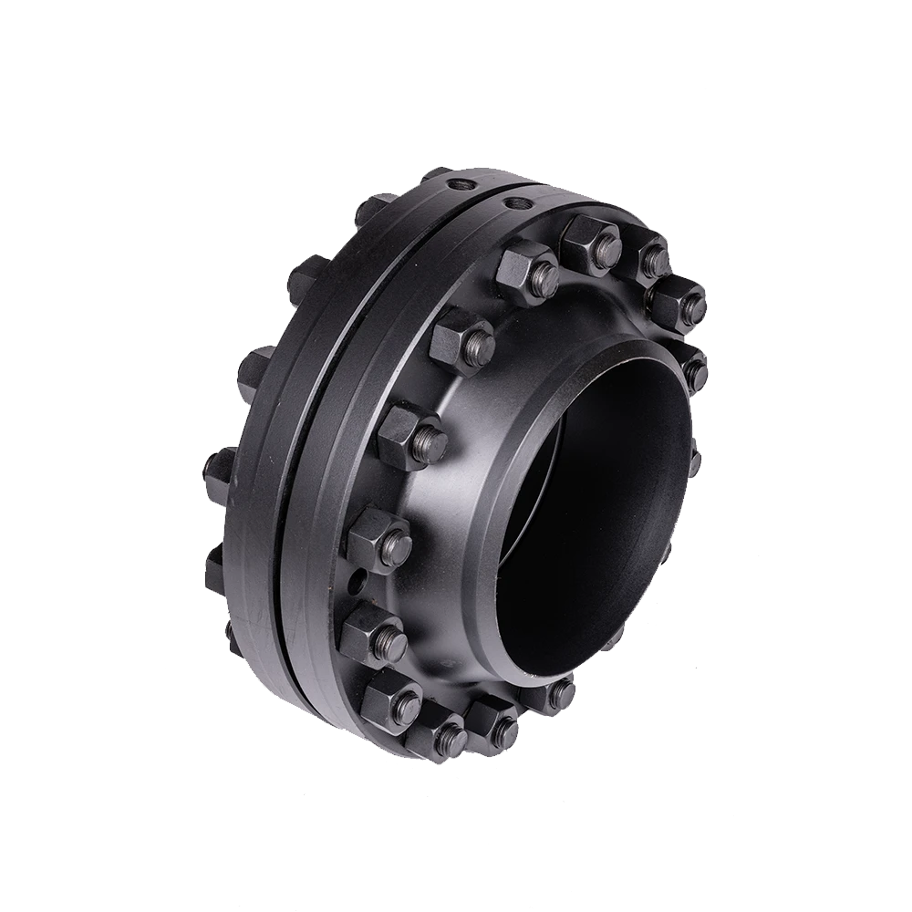

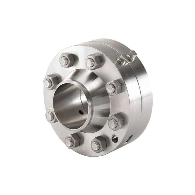
But When Field Crews Modify Orifices. Where flow rate accuracy holds material commercial or legal significance, field engineers see exactly the same vulnerability: the simple, off-the-shelf ANSI-ASME B16.5 flange was never intended to support orifice plates. Field-drilled taps introduce tolerances exceeding the 0.5 mm limit permitted by ANSI-ASME B16.36.
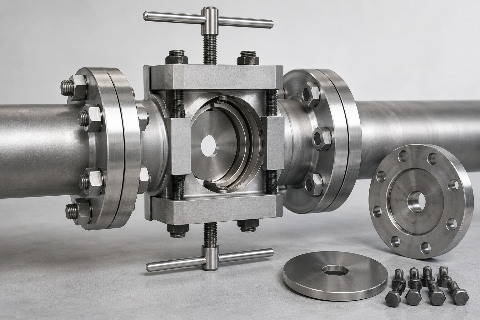
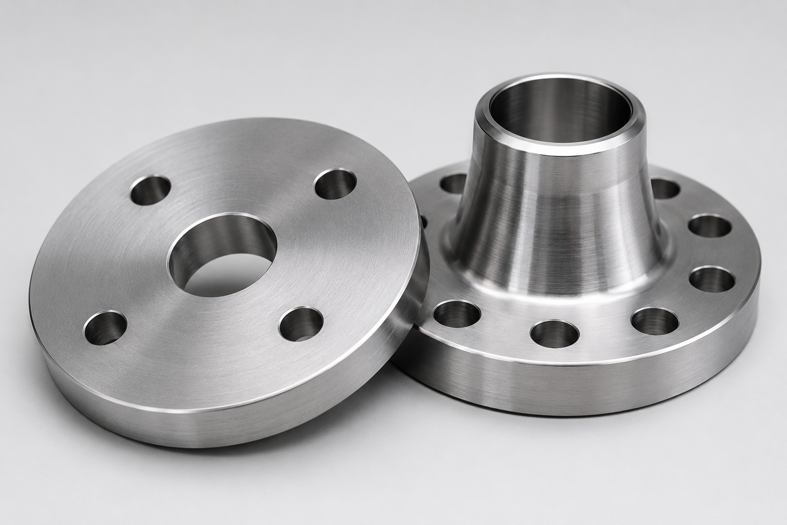
Orifice flanges provide the ultimate answer: holes are machined, not drilled, to the standard with tappings matched precisely before dispatch, and jack screws that allow removal of the orifice plate without pipe separation.
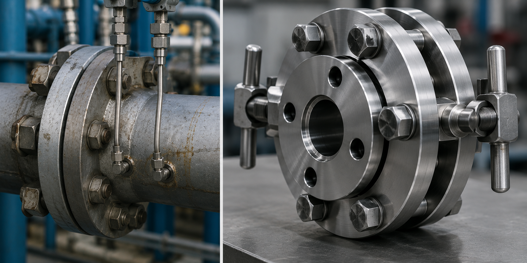
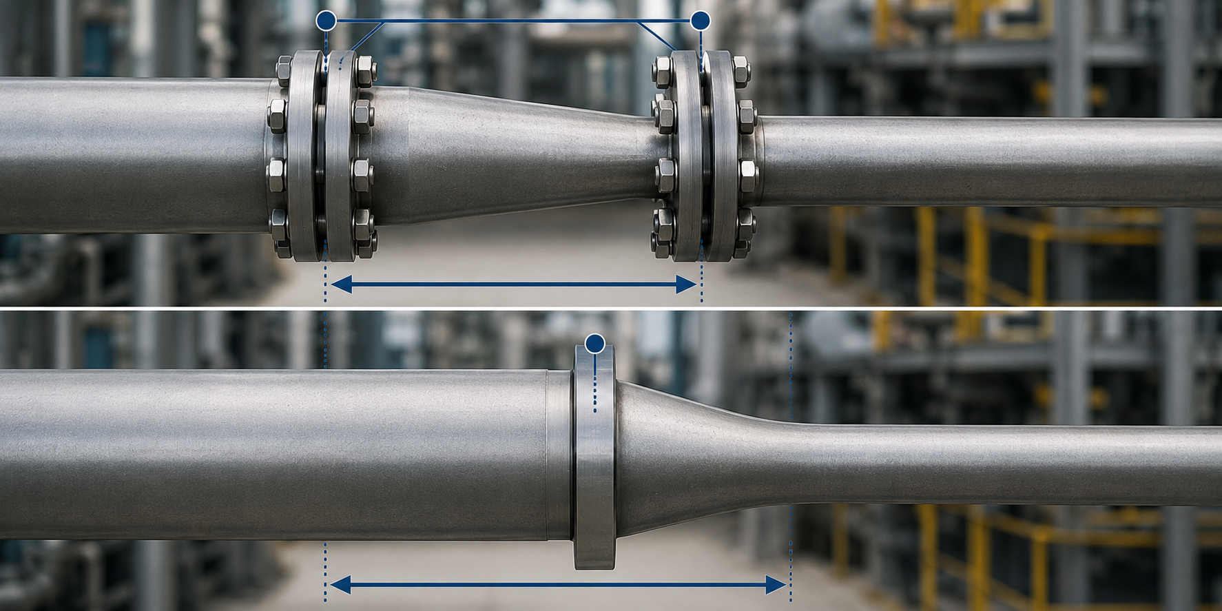
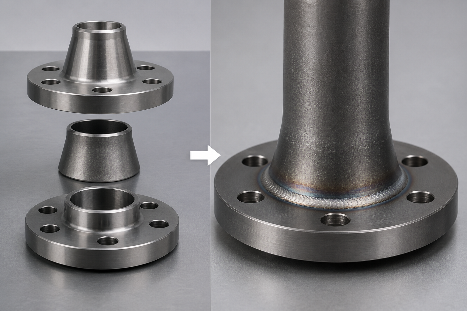
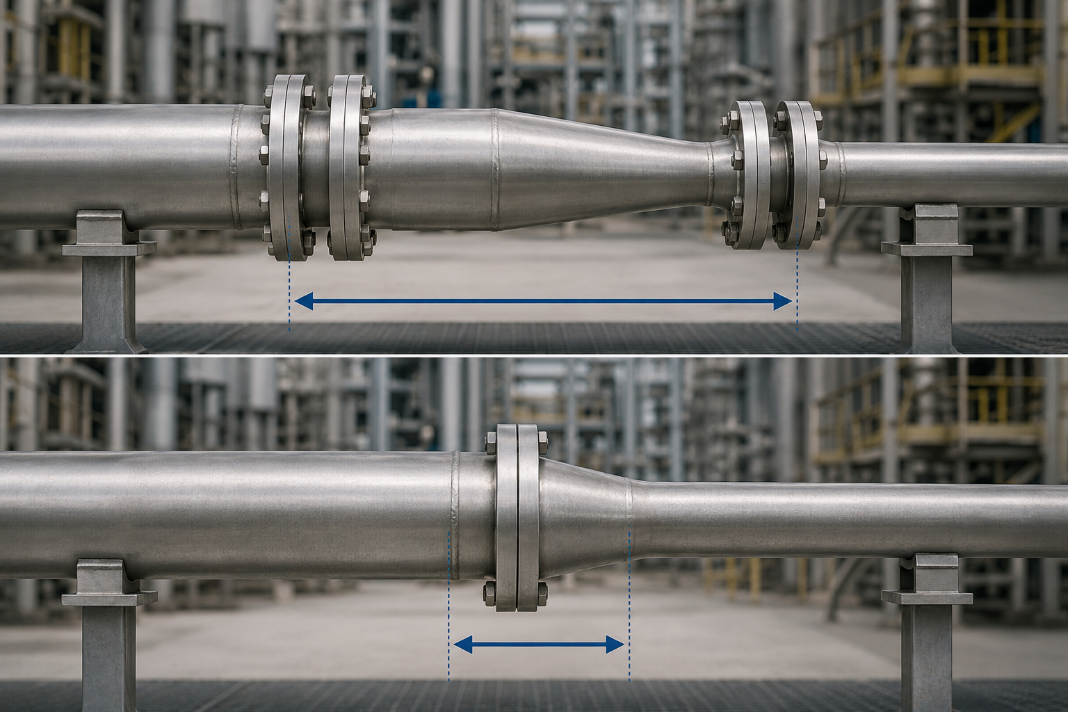
Another challenge is in diameter transitions in busy skid and platform piping. A simple concentric reducer welded in place by two standard flanges gets two items added to the bill of material. In crowded topsides or process skids, length simply doesn’t always exist. A reducing flange combines the diameter change into a single piece of forged hardware; one weld, one flange face, less pipe.
In the case of field-made assemblies failing their orifice measurement, the deficiency isn’t workmanship – it’s fundamental design. Standard B16.5 flanges weren’t meant for the close tolerances of precision tap geometry. A weld neck orifice flange with the correct bore and certified tap location provides AGA-3-compliant geometry, meeting the accuracy requirements of ISO 5167.
REQUEST ENGINEERING DATA| Parameter | Specification |
|---|---|
| Design Standard | ASME B16.36 — Orifice Flanges |
| Flange Types | Weld Neck (Class 300–2500) | Slip On (Class 300) | Threaded (Class 300) |
| Facing | Raised Face (RF) | Ring Type Joint (RTJ) |
| Pressure Class | Class 300, 400, 600, 900, 1500, 2500 — Note: Class 150 is not available (wall thickness insufficient for pressure tap drilling per ASME B16.36) |
| Size Range | 1″ through 24″ NPS (custom larger sizes on enquiry) |
| Pressure Taps | ½″ NPT × 2 per pair, 180° apart — ¾″ or 1″ NPT available on request |
| Tap Position Tolerance | ±0.5 mm for NPS < 4″ | ±0.8 mm for NPS ≥ 4″ (per ASME B16.36) |
| Jack Screws | Supplied per pair — positioned 90° from taps, 180° apart when installed (per ASME B16.36 §5.2) |
| Bore Tolerance | ±0.5% of nominal pipe ID |
| Material Grades | ASTM A105 (CS) | A182 F304/F316/F316L (SS) | A182 F11/F22/F91 (Alloy) | A350 LF2 (Low Temp) | A694 F52/F60/F65 (HPHT) |
| Parameter | Specification |
|---|---|
| Design Standard | ASME B16.5 — Pipe Flanges and Flanged Fittings |
| Flange Types | Weld Neck Reducing | Slip On Reducing | Threaded Reducing |
| Facing | Raised Face (RF) | Ring Type Joint (RTJ) | Flat Face (FF) |
| Pressure Class | Class 150–2500 |
| Size Range | 1″ × ½″ through 24″ × 20″ NPS (custom size combinations available) |
| Typical Application | Inline pipe diameter reduction; replaces concentric reducer + 2 standard flanges with 1 forged component |
| Material Grades | ASTM A105 (CS) | A182 F304/F316 (SS) | A350 LF2 (Low Temp) | A694 F52 (HPHT) |
Here’s how our typical applications, flow conditions, service pressures and materials align with ASME B16.36 selections; also notice our custom selection for your choice of tapping configuration and ASME/ AGA standard. Note that you’ll find nothing approaching this level of specificity on any competitor’s website’s orifice flange product pages, even the top 10 results.
MATRIX // Application × Pressure Class × Material (ASME B16.36)| Application Scenario | Service Conditions | ASME B16.36 Class | Recommended Material | Tap Configuration | Key Standard |
|---|---|---|---|---|---|
| Oil & Gas Custody Transfer (sweet gas) | Natural gas, <70°C, non-sour | Class 300–600 | ASTM A105 (CS) | ½″ NPT flange taps, RF | AGA-3 / API MPMS 14.3 |
| Oil & Gas Custody Transfer (sour service) | H₂S >0.3 kPa partial pressure, NACE conditions | Class 600–900 | A182 F316 or A182 F22 (NACE MR0175) | ½″ NPT flange taps, RF | AGA-3 + NACE MR0175 |
| High-Pressure Steam (≤Class 900) | Steam 260–430°C, 4–10 MPa | Class 600–900 | A182 F11 / F22 (Cr‑Mo alloy) | ½″ NPT flange taps, RTJ facing | ASME B16.36 + ASME B31.1 |
| High-Pressure Steam / HPHT (>Class 900) | Steam >430°C or critical steam; offshore HPHT | Class 1500–2500 | A182 F22 / A182 F91 / A694 F60‑F65 | ¾″ NPT flange taps, RTJ facing | ASME B16.36 + ASME B31.3 |
| Chemical / Petrochemical (corrosive) | Acids, chlorides, Cl⁻ service | Class 300–600 | A182 F316L | ½″ NPT flange taps, RF | ISO 5167 + ASME B16.36 |
| Power Generation (boiler feedwater / condensate) | Demineralized water, ≤150°C | Class 300 | A182 F304 / ASTM A105 | ½″ NPT flange taps, RF | ISO 5167 |
| Water & Wastewater | Treated water, ambient conditions | Class 300 (Class 150 not available — see note) | ASTM A105 | ½″ NPT flange taps, RF | ASME B16.36 |
| Application | Recommended Type | Pressure Class | Material | Key Installation Note |
|---|---|---|---|---|
| Oil & gas inline reduction | Weld Neck Reducing | Class 600–1500 | A105 / A182 F316 | Maintain ≥10D straight pipe before any flow meter downstream |
| High-pressure steam reduction | Weld Neck Reducing | Class 900–2500 | A182 F11 / F22 | RTJ facing required at ≥Class 900 |
| Chemical / corrosive service | WN or SO Reducing | Class 300–600 | A182 F316L | Do not install directly upstream of orifice measurement station |
| Mid-pressure water service | Slip On Reducing | Class 150–300 | ASTM A105 | For non-critical metering lines only |
| Low-temperature service (<‑29°C) | WN or SO Reducing | Class 150–300 | A350 LF2 | Impact tested per ASME B16.5; Charpy certification required |
Orifice flange set vs. field-welded tappings vs. concentric reducer approach
A very prevalent misconception out in the field concerns turbulent flow – many users suspect it might be a source of orifice meter inaccuracy. That’s incorrect; the orifice meter was designed precisely to measure at precisely this condition (most industrial applications operate far beyond Re >4,000, and certainly into what would be considered the high turbulence regime). What kills your measurement is asymmetry- any sort of disturbance- such as a nearby partially closed valve or elbow immediately preceding the orifice meter that creates an uneven velocity distribution; precisely why B16.36 mandates the specified lengths of upstream straight run pipe (10D if used with a flow conditioner and 20D otherwise, but not the condition of the pipe wall surface itself).
An often confusing side effect of an orifice installation: Flow straighteners placed before an orifice station actually can reduce accuracy of measurement. These devices eliminate the flow turbulence that’s inherent in any flow calculation and provide instead persistent velocity imbalance in the smoothed stream. This is why standard AGA-3 recommends sufficiently long runs of straight pipe instead of flow conditioning.
Looking for Orifice flanges for a project? Send us your line specification and we’ll provide you a technical comparison with recommendations on material and pressure class.
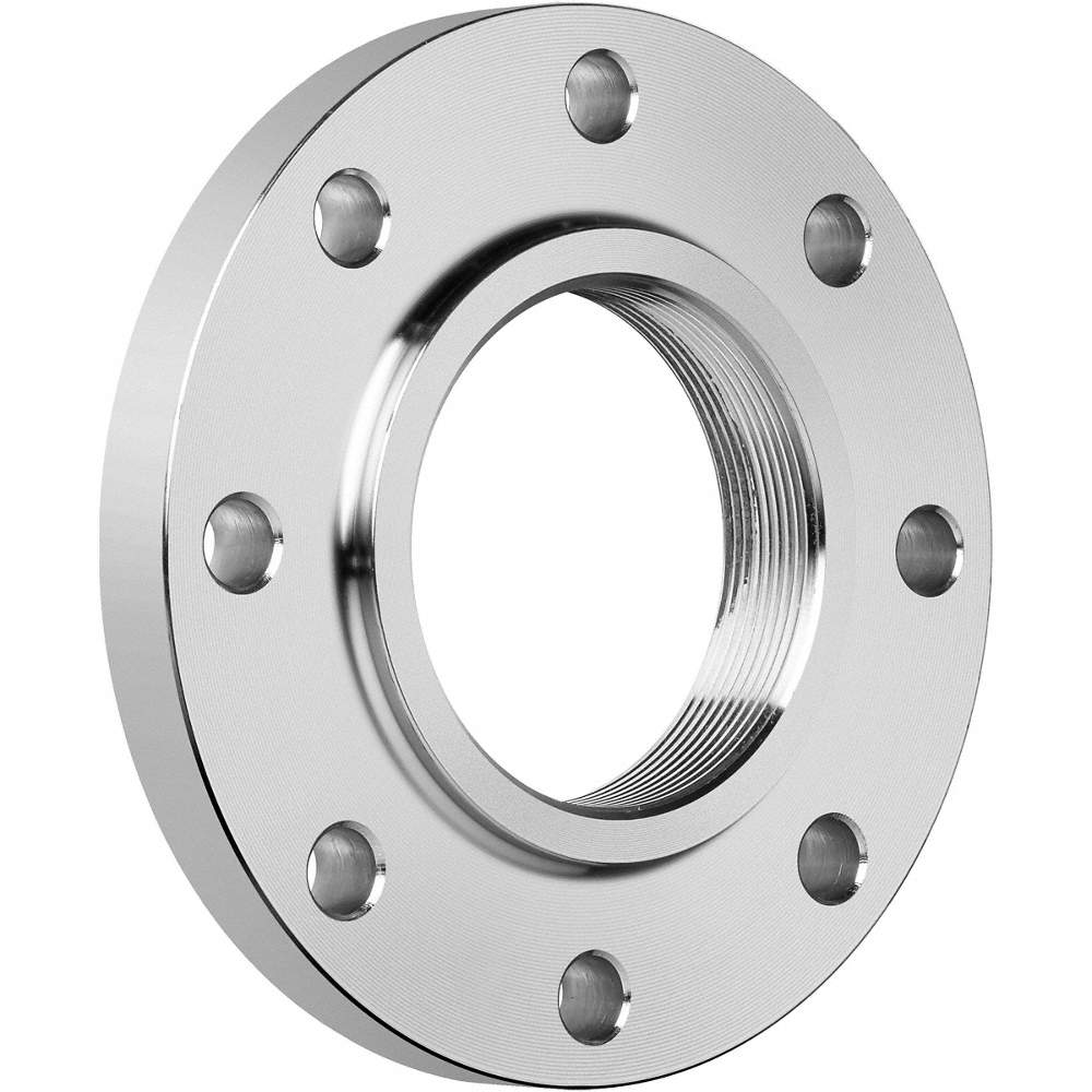
Request Technical ComparisonSynbase Steel Co., Ltd. is a member of E-CHENG STEEL GROUP which was established in 2005 in China. It has the manufacturing bases over 70,000m with exclusive forge lines and two powerful forging presses, a 6,000 tons press and a 2,000 tons press, all for flanges production. Raw materials supply is guaranteed through long-term relationships with the China’s three largest steelmakers: Baosteel, TPCO and Ansteel, ensuring traceability of heat of material from the mill certificate all the way down to the finished product.
With 800+ national patents in pipe fittings, flange and valve production, our parent company registers a total annual sales volume in excess of 30 billion RMB. Synbase represents the international products marketing department specialized in special flange, fitting and piping for energy, petrochemical and power projects around the globe.
| Client / Project | Region | Product Category | Supply Period |
|---|---|---|---|
| Kuwait National Petroleum Company (KNPC) | Middle East | Carbon steel and alloy flanges, fittings | 2015–present |
| SONATRACH (Algeria) | North Africa | Strategic materials supply — flanges and piping components | Active |
| PTT Group (Thailand) — affiliated contractors | Southeast Asia | Energy sector flange supply | Active |
So far, Synbase has exported our products to over 100 countries worldwide, including Southeast Asia, the Middle East, Europe and America, to EPC, NOC and independent refineries and power plants.

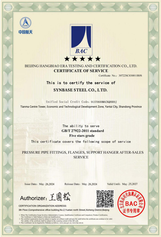
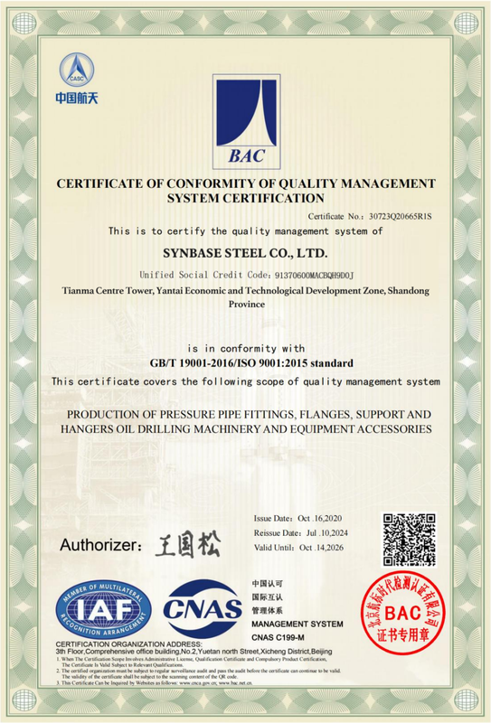
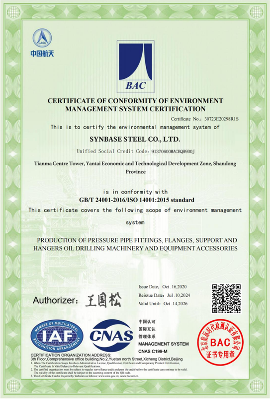
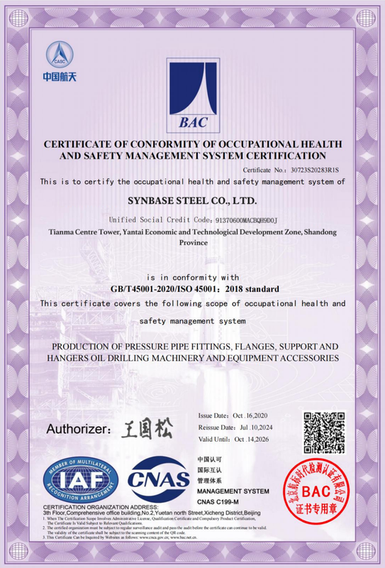

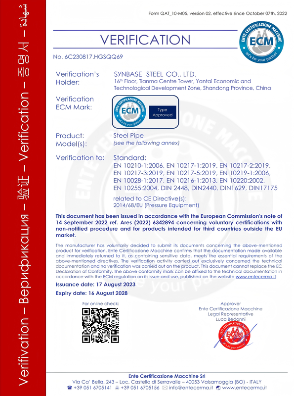
| Category | Standard / Specification | Scope |
|---|---|---|
| Flange Design | ASME B16.36 | Orifice flanges — dimensional and pressure class requirements |
| Flange Design | ASME B16.5 | Reducing flanges — pressure-temperature ratings and dimensions |
| Material — Carbon Steel | ASTM A105 / A105M | Carbon steel forgings for piping applications |
| Material — Alloy / Stainless | ASTM A182 / A182M | Forged or rolled alloy-steel pipe flanges, F304/316/316L/F11/F22/F91 |
| Material — Low Temp | ASTM A350 LF2 | Low-temperature carbon-steel forgings; Charpy impact tested |
| Material — HPHT | ASTM A694 F52 / F60 / F65 | High-yield carbon and alloy steel forgings for high-pressure gas transmission |
| Pressure Testing | ASME B16.5 Annex E | Hydrostatic shell test protocol; test certificates supplied standard |
| Material Certification | EN 10204 Type 3.1 / Type 3.2 | MTR certified by manufacturer’s authorized inspector; 3.2 by BV/TUV/SGS |
| Positive Material ID | ASTM E1476 (PMI) — XRF | Alloy verification on finished flanges; included for F316, F22, and HPHT grades |
| Flow Metering | AGA-3 / API MPMS Chapter 14.3 | Orifice metering calculation methodology for natural gas |
The minimum documentation requirement on any pressure boundary component for the oil and gas industry (including power generation and petrochemical industries) is an EN 10204 Type 3.1, based on prevailing standards of EPC contracts. A Type 3.1 report is one certified by an independently appointed material manufacturer’s inspector with the authority to confirm testing (chemical and physical properties tested according to the specified standards, i.e. ASTM) and with full traceability of each component’s heat to the associated mill material certificate.
To ensure you get the right orifice flanges for your project. EN 10204 Type 3.2 is needed for high-criticality subsea, nuclear and HP/HT applications. EN 10204 Type 3.2 adds third-party witness inspections by an independent inspecting body (BV, TUV, SGS). Our EN 10204 Type 3.1 certified laboratory under CNAS covers both levels, but EN 10204 Type 3.2 orders often add 2-4 weeks to standard lead time due to this third party requirement.
Need samples, PMI results or confirmation on the scope of certification to meet EN 10204 Type 3.1 requirements before placing purchase order?
Request Compliance DocumentationCost is weighted as just 15-20% of the total score on an EPC supplier selection matrix -with quality, documentation and technical capability combined accounting for up to 50-60% of the score. More commonly, the “cheapest” orifice flanges are actually the most expensive components on a project; ones that show up out-of-spec on material certification, create inspection delays, or have missing documentation that pushes the project timeline into liquidated damages.
Compromising on documentation depth – substituting EN 10204 Type 2.2 for an required 3.1, skipping PMI verification on high nickel alloys, or opting for mill-run tolerances over required shop tolerance-is rarely an option once the piping has been assembled. The industry truth is that documentation failures emerge at the most inconvenient time: during third-party inspections, during pre-commissioning,or at client hand-off.
“One problematic supplier, one missing document, or one non-compliant weld can burn weeks of schedule and push your project into liquidated damages territory.”— Industry procurement guidance
Streamline your engineering workflow with our interactive utilities. Calculate dimensional specifications, compare installation footprints, and generate compliant documentation packages instantly.
ASME B16.36 — Determine pressure class, tap size & material combinations for your specific application.
Launch SelectorCompare BOM, pipe run length, weld count and flow meter suitability for your transition.
Compare OptionsEN 10204, PMI, CoC & inspection certificates — ascertain what your specific project actually requires.
Build PackageAn orifice flange is used to attach an orifice plate to two flanges that will be placed between two parallel lines to enable meter measurement (e.g. flow or temperature). The use of two tap holes in the same flanges allows you to measure flow. There are three ASME pressure tap configurations, but the ones used most regularly are the “two-tap” ASME B16.36 orifice flange configuration. The orifice flange has precisely machined “NPT tapped holes” or “¼ inch taps” in two places at a ninety-degree angle to one another on the same pipeline, where differential flow can enter the measuring device. On these, the “taps are placed 180 degrees apart, one in the primary orifice plate,” and,”one on the pipe itself” which allows for measuring and calculating flow based on either the AGA-3 and ISO 5167 methodology.
A single, flange type piece used to connect two pipes of different diameter. Unlike concentric reducers and two flanges, the reducing flange consists of a one-piece design that simplifies the BOM and construction of a pipeline. Reducing flanges are used to save space and weight and to simplify connections, particularly on high pressure, but not high temperature, and high toxicity process pipe lines. Due to the increased flow turbulence created at the transition diameter reduction, the reducing flange isn’t suitable for locations immediate upstream of sensitive measurement devices such as, orifice meter runs, ultrasonic, Coriolis and other flow meters. It’s common practice to require a minimum 10 pipe diameters straight line section (the same length as the pipe diameter x10) to smooth the flow before a flow meter where a reducing flange has been used.
The one-piece construction results in a more drastic change in diameter than a tapered concentric reducer, which tends to increase flow turbulence for several diameters downstream of the transition. Because of the turbulence increase, a reducing flange can’t be installed immediately upstream of an orifice plate run, an ultrasonic flow meter or a Coriolis meter. A minimum of 10 pipe diameters (10 x Pipe Outer Diameter) is required to transition back to the process fluid so as to not disrupt sensitive flow measuring instruments.
Because the wall thickness of a Class 150 flange isn’t thick enough to allow for proper NPT pressure tap hole machining, while at the same time ensuring the required metal engagement depth, Class 150 flange is excluded in ASME B 16. 36. The minimum pressure class for orifice flange in accordance with ASME B 16. 36 is Class 300 for all kinds of connection. Low pressure water and process applications that might call for a Class 150 can use a Class 300 orifice flange, which has enough wall thickness while still conforming to the pressure limitations for the corresponding Class 150 piping.
When Installing FlangePair Install orifice flanges as a matched pair. Align jack screws at 90 degrees relative to the pressure taps (the two jack screws will be opposite each other 180 degrees apart). Make sure orifice plate is concentric with bore. Ensure bore is within 0.5 % of the pipe ID (inner diameter). Torquewas made in a cross pattern in according to manufacturer specification. Connect pressure tap tubing with NPT fitting.Ensure orifice plate flows directedtoward the proper direction of the arrow indicator on the orifice plate.If used for AG A-3 metering applications, make surethe up stream piping will provide required 20D minimum of straight pipe (or 10D with flow conditioner if available).
Yes. Synbase specializes in custom orifice flanges, manufactured to specifications in exotic alloys not listed on ASME B16.36. These include Inconel 625, Duplex 2205, and Super Duplex 2507 alloys for particularly difficult corrosive applications and high pressure / high temperature applications. Each custom order require a minimum of 1 pair. Our team work with each client to prepare an engineering drawing for review and approvals, and can manufacture custom dimensions for any combination of pipe sizes within the capability of our forge press capabilities.
ISO 9001 Quality Certificate; EN 10204 Type 3.1 Material Test Report (including mechanical property and chemical analysis, certified by the authorized inspector for material manufacturer); Certificate of Conformity; Dimension Inspection Report; Hydrostatic Test Certificate. The following extras are available at an extra cost: EN 10204 Type 3.2 (third party witnessed by BV / TUV / SGS); PMI XRF Test Report; Certificate of Conformity with NACE MR0175 requirement; Heat Number Verification Sheet.