Send Your RFQ to Synbase Steel
Prefer to send drawings, BOMs or attachment lists by email? sales@synbasesteel.com

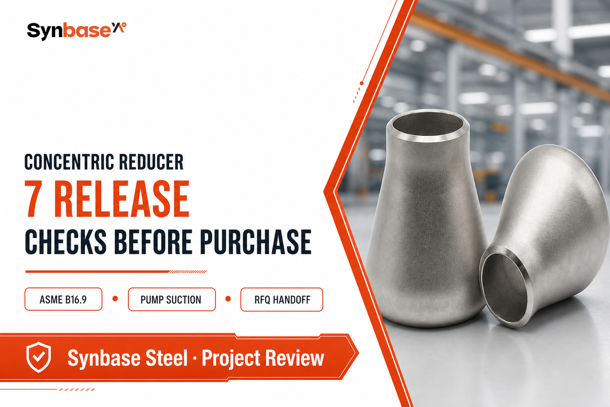
Concentric Reducer is a pipe fitting that aligns the pipe axes while changing size. Its release decisions should be treated as piping-system decisions, not as a diameter-only purchase choice. A common centreline is only one part of the picture: the connected equipment, service phase, required flow path, governing documents, and unresolved risks can change what a safe release record needs to show.
Updated July 2026. Public-source guide for project review; it doesn’t replace the approved piping design, welding procedure, inspection plan, or site-safety requirements.
A concentric reducer is a conical pipe fitting whose larger and smaller ends share a common centreline. That definition answers a geometry question; it doesn’t settle a piping-system question. This guide is deliberately about the review that happens before a technical handoff: what needs to be decided, evidenced, or escalated before a fitting request is released.
That distinction matters because the existing commercial resource already covers the things a buyer expects from a product page: product range, material options, dimensions, and a request-for-quotation path. For the pipe-material background that sits behind that handoff, see the stainless steel pipe guidance. Repeating those modules here would add pages without adding a better decision. This article instead follows the point where a drawing, a standard reference, and a process risk meet.
Once that review has set a clear requirement, use the concentric reducer product page for material, dimension, and sourcing details; it does not replace the project release record.
Early research often begins with labels such as concentric pipe reducer, concentric reducer fitting, or concentric vs eccentric reducer. The release question is narrower: what operating condition, drawing revision, and evidence must travel with that label? This guide also addresses the practical questions “What is a concentric reducer?”, “What is the difference between concentric and eccentric reducers?”, and “Why use an eccentric reducer?” by separating geometry from a project-specific decision.
A release record can still name the product facts that affect the decision. For example, concentric and eccentric reducers have a different pipe’s centerline; a larger end and a smaller pipe create a smooth transition, but the connection, wall thickness, material, and direction still need to agree with the drawing. Carbon steel, stainless steel, Schedule 40S, a butt weld, and whether teams weld concentric reducers belong in the technical handoff when relevant. They don’t, on their own, reduce the need to resolve a flat top or bottom orientation in a sensitive service.
In chemical processing or another controlled service, the pipe’s centerline, flow and pressure design basis, and any inch-based drawing convention should be read from the approved project documents rather than guessed from a generic fitting label.
The published ASME B16.9 scope is useful at this boundary: it identifies what a fitting standard covers without supplying a project’s operating basis or release authority.
| Question | This guide | Product specification resource |
|---|---|---|
| Primary job | Release-control education | Product and sourcing information |
| Main risk | An unresolved design condition | An incomplete product request |
| Next action | Assign an owner and hold point | Request the applicable product details |
Takeaway: do the design release first. A product request become clearer once the system conditions are documented.
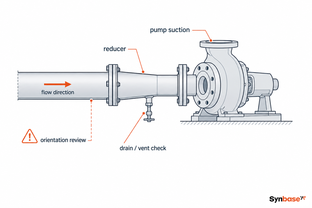
At a pump suction, a concentric reducer should trigger a review of inlet conditions rather than an automatic approval or rejection. A University of Pretoria study modelled 12 pump-suction reducer geometries at four inlet velocities; its value here isn’t a universal geometry prescription, but a clear warning that approach flow, reducer angle, air transport, and inlet-flow distribution interact.
That’s why “use this type on vertical pipe and that type on horizontal pipe” is too thin to become a release record. The U.S. Department of Energy pumping-system sourcebook identifies improper flow profile, vapor collection, and vortex formation as piping-configuration concerns. Those are system behaviours. A reducer can be part of the condition, but it isn’t the whole explanation.
“The useful question is not ‘Which reducer is normally used?’ but ‘Which inlet condition has been demonstrated for this service and layout?’”
Design-review note based on the University of Pretoria pump-suction CFD study and the U.S. DOE pumping-system sourcebook
A fire-pump arrangement show why scope matters. A City of Miami 2022 plan-review guideline treated a 10 pipe-diameter suction arrangement and an eccentric reducer as distinct requirements in its fire-pump/NFPA 20 context. That historical illustration isn’t a current design basis for every process line: a project must confirm its governing edition and jurisdiction. It shows how a code-bound application can turn a familiar fitting choice into a specific release item.
Takeaway: when the reducer approaches a pump, a tank outlet, or another sensitive inlet, record the operating condition and escalate the geometry to the responsible piping review.
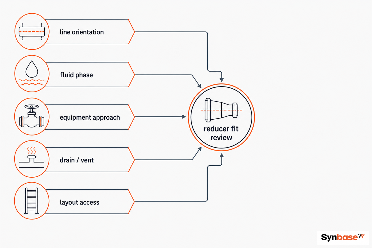
This 5-Input Reducer Fit Matrix starts with service phase, equipment approach, upstream disturbance, air or vapor path, and available straight run; the wider map turns those inputs into nine release prompts. It’s meant to reveal what must be checked before the drawing is released, not to replace hydraulic calculation or current project standards.
The prompts are deliberately system-level: the U.S. Department of Energy pumping-system sourcebook likewise treats inlet flow profile, vapor collection, and layout as connected piping concerns.
| Review prompt | Why it can change the decision | Owner before release |
|---|---|---|
| 1. Service phase | Liquid, gas, vapor, solids, or mixed service can change what must be avoided. | Process/piping design |
| 2. Equipment approach | A pump inlet is not a generic line transition. | Piping design |
| 3. Upstream disturbance | A nearby bend, valve, or branch can alter approach flow. | Piping design |
| 4. Air or vapor path | Accumulation risk needs a documented response, not a remembered rule. | Process/piping design |
| 5. Available straight run | Some application standards address approach layout explicitly. | Piping design |
| 6. Drawing revision | An orientation call without a controlled drawing cannot be verified at fit-up. | Document control |
| 7. Governing code | B16.9 scope and the project piping code answer different questions. | Design authority |
| 8. Inspection hold point | A late discovery can create rework after alignment or weld preparation. | Quality assurance |
| 9. Unresolved condition | A known uncertainty should stay open and assigned, not disappear in procurement notes. | Named evidence owner |
Keeping the list this explicit has a practical benefit. A request may be technically correct for a simple vertical transition yet still be incomplete for a pump inlet, a gas-bearing line, or a revised drawing. The decision shifts from “concentric or eccentric?” to “what condition has this fitting been released against?”
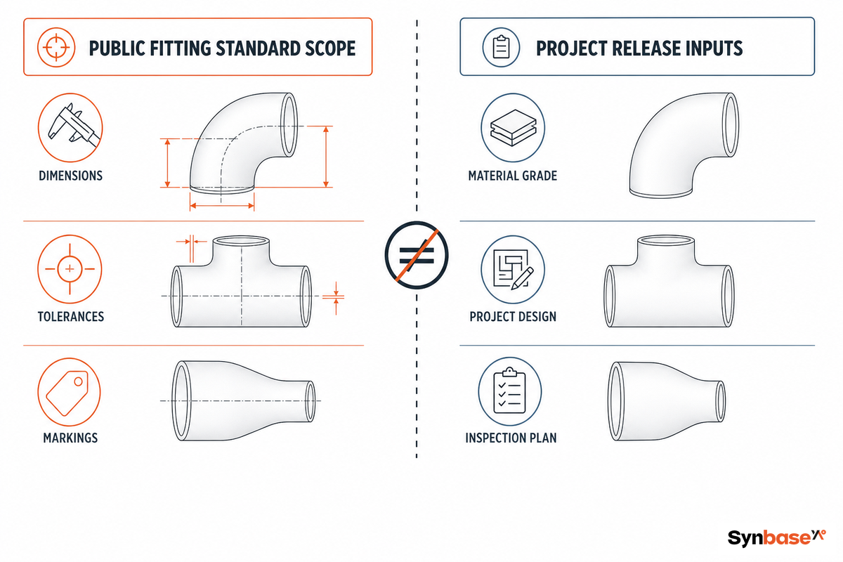
ASME B16.9-2024 defines a public scope for factory-made wrought butt-welding fittings, including overall dimensions, tolerances, ratings, testing, and markings. Its published range is NPS 1/2 through NPS 48; the page also identifies exclusions and says the standard is used with other ASME B16, BPVC, and B31 materials.
That’s a valuable boundary, but it isn’t a complete project release. The public standard page doesn’t give a project its governing drawing revision, service classification, welding procedure, inspection plan, or approval owner. Treating a fitting-standard reference as if it did can make a submittal look complete while the release decision is still open.
Don’t read the NPS range as a field measurement or a fitting catalogue. When a controlled record need size language, it can preserve the nominal designation, NPS 1/2 in, 1 in, 2 in, 3 in, 4 in, 6 in, 8 in, 12 in, 16 in, 24 in, 36 in, or 48 in—and point back to the project-controlled geometry and wall details. The point is traceability, not a substitute dimension table.
| Item | Release label | What to do |
|---|---|---|
| Fitting dimensions | Standard-controlled | Reference the applicable edition and project requirement. |
| Tolerance and marking scope | Standard-controlled | Confirm the stated scope is applicable. |
| Piping-code application | Project-controlled | Name the governing code and design authority. |
| Service and pressure case | Project-controlled | Keep the design basis with the release record. |
| Welding and fit-up control | Project-controlled | Route to the approved procedure and inspection plan. |
| Inspection hold point | Project-controlled | Assign the person who can release work onward. |
| Supplier confirmation | Supplier-confirmed | Request only after the project boundary is clear. |
| Evidence category | Published fact | Release boundary |
|---|---|---|
| Standard edition | B16.9-2024 is publicly listed by ASME. | Record the edition used by the project. |
| Scope range | NPS 1/2 through NPS 48 is the stated range. | Do not infer a project dimension. |
| Modelled pump study | 12 geometries were assessed. | Use as a review prompt, not a universal rule. |
| Modelled inlet cases | 4 inlet velocities were included. | Project flow conditions remain separate. |
| University fitting tests | 60 fittings from 7 manufacturers were tested. | Do not transfer a loss value to another layout. |
| Fire-pump review | 10 pipe diameters appear in a Miami guideline. | That requirement is limited to its fire-pump scope. |
| EU pressure boundary | 0.5 bar is cited in EU trade guidance. | Confirm jurisdiction and equipment category. |
| Drawing control | A fitting label cannot identify the approved revision. | Name the controlled drawing and owner. |
| Inspection control | A generic standard cannot assign a site hold point. | Keep the hold point in the project plan. |
Takeaway: a standard reference is necessary evidence, but it doesn’t remove the need for project-controlled evidence.
A release meeting work when each condition has one owner and one visible next action. Piping design decides the basis; quality assurance defines the hold point and evidence check; procurement carries the released record into the product request without rewriting engineering intent.
These roles shouldn’t be flattened into a generic “approval.” A design engineer may understand why a reducer orientation changed. A quality reviewer may know which record needs to be present at fit-up. A procurement professional may be the first person to discover that the handoff says “concentric reducer” but omits the drawing revision or the condition that triggered the choice.
The separation starts with a real technical boundary: the published ASME B16.9 scope doesn’t assign a project drawing owner, inspection hold point, or procurement release authority.
Takeaway: a condition isn’t closed because everyone has seen it. It’s closed when the responsible role, evidence, and hold point are named.
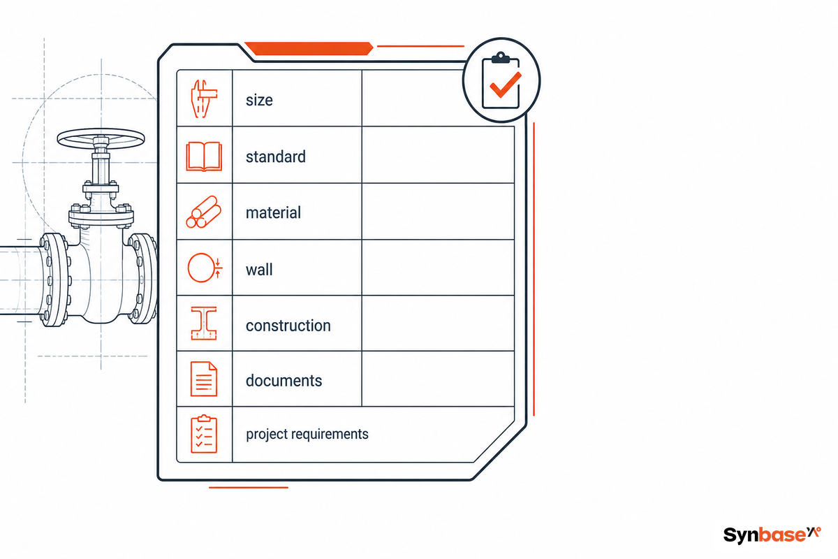
A 7-Field Reducer Handoff Card is a compact record that carries the engineering decision into quality and procurement. It isn’t an RFQ checklist and it doesn’t ask a supplier to choose the design; it records what the project has already decided or still needs to resolve.
Its standard-edition field should point to the published ASME B16.9 reference while the remaining fields preserve the project-specific decision trail.
| Field | Record before release | Owner |
|---|---|---|
| 1. System/service context | Fluid condition, equipment context, and design basis reference. | Piping design |
| 2. Governing documents | Code, standard edition, and controlled drawing revision. | Design authority |
| 3. Geometry decision | Concentric or eccentric choice and its stated rationale. | Piping design |
| 4. Inlet-risk trigger | Pump, air/vapor, layout, or other condition requiring review. | Piping design |
| 5. Hold point | An inspection or approval point that prevents uncontrolled fit-up. | Quality assurance |
| 6. Evidence owner | Person accountable for the required project evidence. | Named role |
| 7. Unresolved condition | Open item, due date, and escalation route. | Named role |
| Control A. Release status | Released, held, or returned for engineering review. | Quality assurance |
| Control B. Handoff record | Attach the controlled record to the sourcing package. | Procurement |
Once the seven fields are resolved, the project can move to the commercial layer with less ambiguity. For product-level information after that handoff, use the concentric reducer product specifications.
Takeaway: a good handoff preserve why the fitting was chosen, not merely what it’s called.
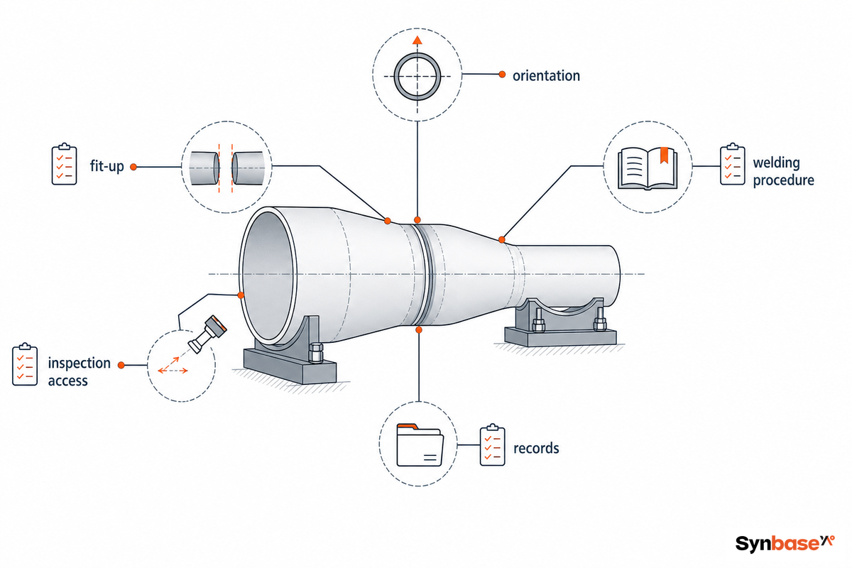
Before fit-up and welding, verify that the released orientation matches the controlled drawing, the flow path hasn’t changed, the required evidence is present, and any open condition has an owner. This is a release-control check, not a substitute for the approved welding procedure or inspection plan. For a sensitive pump approach, the DOE pumping-system sourcebook is a systems-level reminder to reopen the condition rather than rely on a fitting label.
Takeaway: the highest-value field question is often “what changed since design release?” A changed condition can matter more than a fitting label.
For 2026 projects, the practical trend isn’t a market-growth statistic; it’s tighter documentation discipline. ASME publicly lists B16.9-2024 as the current edition on its product page, so a release record should state the edition being used and identify the separate project controls that remain open.
That boundary become more important in regulated contexts. European Commission trade guidance describes pressure equipment, piping, safety accessories, and pressure accessories above 0.5 bar as products that can fall within design, manufacture, and conformity-assessment requirements. Applicability depends on the jurisdiction and equipment category; this is a review prompt, not a declaration that every reducer has the same compliance route.
For a new project, make the action simple: keep the governing code, controlled drawing, applicable conformity route, inspection owner, and unresolved condition together. Don’t replace them with a forecast, a generic certificate request, or a remembered orientation rule.
This article uses public sources and doesn’t claim project results, supplier performance, material certification, or universal hydraulic limits. Where a source describes a specific pump, fire-protection, or modelled condition, the text preserve that boundary.
Synbase Steel supplies steel pipe, fittings, flanges, valves and OCTG for oil and gas, petrochemical, power, water and industrial projects. Our technical guides are written to help buyers compare standards, grades, dimensions, coatings, inspection requirements and commercial terms before sending an RFQ.
We focus on practical specification work: matching pipe process to service conditions, checking wall thickness and end finish, reviewing MTC and NDT requirements, and clarifying documentation before production or shipment.
Project support across seamless pipe, ERW, LSAW, SSAW, buttweld fittings, forged flanges, valves and oilfield tubulars.
Specification review for ASTM, ASME, API, EN and DIN standards, including material grade, pressure class, coating and inspection scope.